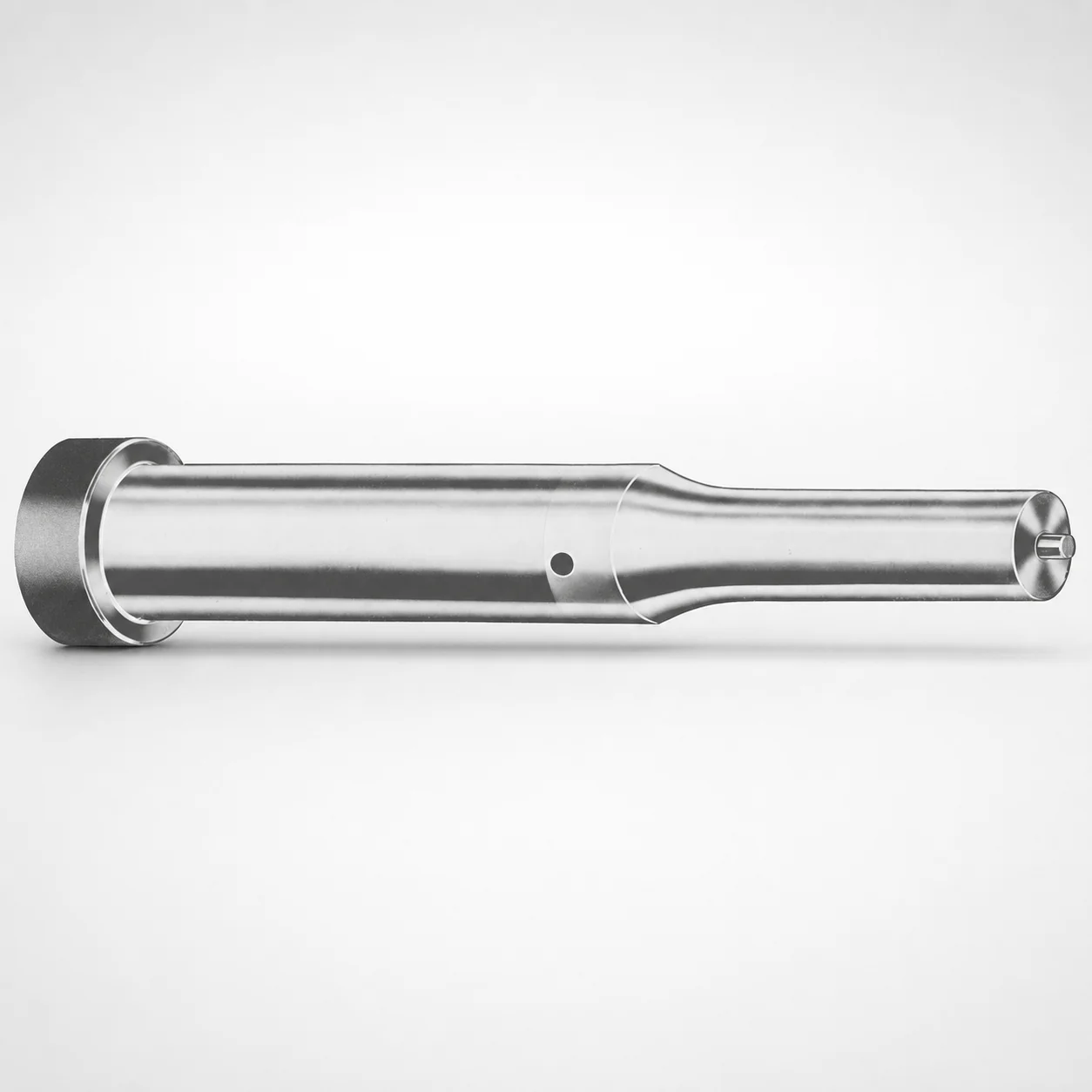
Ejector Punches Metric XCDP Coating
Ejector Punches Metric XCDP Coating deliver consistent part ejection performance in precision tooling. The XCDP coated surface helps reduce wear and supports reliable punch life under repetitive cycles.
- Metric ejector punch geometry for stable ejection in close-space applications
- XCDP coating for improved surface wear resistance and tool durability
- Accurate point options support repeatable contact and consistent stroke control
- Used in injection mold and die tooling for efficient, controlled ejection
Specifications
367 configurations available
| Tip shape | Material | D (Shank dia.) (mm) | Jektole group | L1 (Point Length) (mm) | L (Length) (mm) | P Dimension (mm) | W Dimension (mm) | R Dimension (mm) |
|---|---|---|---|---|---|---|---|---|
| H | M2 | 05 | J2M | 13 ~ 19 | 40 ~ 80 | 1.6 ~ 4.95 | 1.6 ~ 4.95 | - |
| H | PS | 05 | J2M | 13 ~ 19 | 40 ~ 80 | 1.6 ~ 4.95 | 1.6 ~ 4.95 | - |
| H | M2 | 06 | J3M | 13 ~ 19 | 40 ~ 100 | 2 ~ 5.95 | 2 ~ 2.39 | - |
| H | M2 | 06 | J3M | 13 ~ 19 | 40 ~ 100 | 2 ~ 5.95 | 2.4 ~ 5.95 | - |
| H | PS | 06 | J3M | 13 ~ 19 | 40 ~ 100 | 2 ~ 5.95 | 2 ~ 2.39 | - |
| H | PS | 06 | J3M | 13 ~ 19 | 40 ~ 100 | 2 ~ 5.95 | 2.4 ~ 5.95 | - |
| H | M2 | 08 | J4M | 19 ~ 25 | 50 ~ 100 | 3 ~ 7.95 | 3 ~ 3.19 | - |
| H | M2 | 08 | J4M | 19 ~ 25 | 50 ~ 100 | 3 ~ 7.95 | 3.2 ~ 7.95 | - |
| H | PS | 08 | J4M | 19 ~ 25 | 50 ~ 100 | 3 ~ 7.95 | 3 ~ 3.19 | - |
| H | PS | 08 | J4M | 19 ~ 25 | 50 ~ 100 | 3 ~ 7.95 | 3.2 ~ 7.95 | - |
| H | M2 | 10 | J6M | 19 ~ 25 | 50 ~ 100 | 4 ~ 9.95 | 4 ~ 4.49 | - |
| H | M2 | 10 | J6M | 19 ~ 25 | 50 ~ 100 | 4 ~ 9.95 | 4.5 ~ 9.95 | - |
| H | PS | 10 | J6M | 19 ~ 25 | 50 ~ 100 | 4 ~ 9.95 | 4 ~ 4.49 | - |
| H | PS | 10 | J6M | 19 ~ 25 | 50 ~ 100 | 4 ~ 9.95 | 4.5 ~ 9.95 | - |
| H | M2 | 13 | J6M | 19 ~ 25 | 50 ~ 100 | 4 ~ 12.95 | 4 ~ 5.99 | - |
| H | M2 | 13 | J6M | 19 ~ 25 | 50 ~ 100 | 4 ~ 12.95 | 6 ~ 12.95 | - |
| H | PS | 13 | J6M | 19 ~ 25 | 50 ~ 100 | 4 ~ 12.95 | 4 ~ 5.99 | - |
| H | PS | 13 | J6M | 19 ~ 25 | 50 ~ 100 | 4 ~ 12.95 | 6 ~ 12.95 | - |
| H | M2 | 16 | J9M | 19 ~ 25 | 50 ~ 100 | 6 ~ 15.95 | 6 ~ 7.19 | - |
| H | M2 | 16 | J9M | 19 ~ 25 | 50 ~ 100 | 6 ~ 15.95 | 7.2 ~ 15.95 | - |
| H | PS | 16 | J9M | 19 ~ 25 | 50 ~ 100 | 6 ~ 15.95 | 6 ~ 7.19 | - |
| H | PS | 16 | J9M | 19 ~ 25 | 50 ~ 100 | 6 ~ 15.95 | 7.2 ~ 15.95 | - |
| H | M2 | 20 | J9M | 19 ~ 25 | 50 ~ 100 | 6 ~ 19.95 | 6 ~ 7.99 | - |
| H | M2 | 20 | J9M | 19 ~ 25 | 50 ~ 100 | 6 ~ 19.95 | 8 ~ 19.95 | - |
| H | PS | 20 | J9M | 19 ~ 25 | 50 ~ 100 | 6 ~ 19.95 | 6 ~ 7.99 | - |
| H | PS | 20 | J9M | 19 ~ 25 | 50 ~ 100 | 6 ~ 19.95 | 8 ~ 19.95 | - |
| H | M2 | 25 | J9M | 19 ~ 25 | 50 ~ 100 | 6 ~ 24.95 | 6 ~ 8.99 | - |
| H | M2 | 25 | J9M | 19 ~ 25 | 50 ~ 100 | 6 ~ 24.95 | 9 ~ 24.95 | - |
| H | PS | 25 | J9M | 19 ~ 25 | 50 ~ 100 | 6 ~ 24.95 | 6 ~ 8.99 | - |
| H | PS | 25 | J9M | 19 ~ 25 | 50 ~ 100 | 6 ~ 24.95 | 9 ~ 24.95 | - |
| H | M2 | 32 | J12M | 25 ~ 30 | 63 ~ 100 | 7.2 ~ 31.95 | 7.2 ~ 9.99 | - |
| H | M2 | 32 | J12M | 25 ~ 30 | 63 ~ 100 | 7.2 ~ 31.95 | 10 ~ 31.95 | - |
| H | PS | 32 | J12M | 25 ~ 30 | 63 ~ 100 | 7.2 ~ 31.95 | 7.2 ~ 9.99 | - |
| H | PS | 32 | J12M | 25 ~ 30 | 63 ~ 100 | 7.2 ~ 31.95 | 10 ~ 31.95 | - |
| J | M2 | 05 | J2M | 13 ~ 19 | 40 ~ 80 | 1.6 ~ 4.95 | 1.6 ~ 4.95 | - |
| J | PS | 05 | J2M | 13 ~ 19 | 40 ~ 80 | 1.6 ~ 4.95 | 1.6 ~ 4.95 | - |
| J | M2 | 06 | J3M | 13 ~ 19 | 40 ~ 100 | 2 ~ 5.95 | 2 ~ 2.39 | - |
| J | M2 | 06 | J3M | 13 ~ 19 | 40 ~ 100 | 2 ~ 5.95 | 2.4 ~ 5.95 | - |
| J | PS | 06 | J3M | 13 ~ 19 | 40 ~ 100 | 2 ~ 5.95 | 2 ~ 2.39 | - |
| J | PS | 06 | J3M | 13 ~ 19 | 40 ~ 100 | 2 ~ 5.95 | 2.4 ~ 5.95 | - |
| J | M2 | 08 | J4M | 19 ~ 25 | 50 ~ 100 | 3 ~ 7.95 | 3 ~ 3.19 | - |
| J | M2 | 08 | J4M | 19 ~ 25 | 50 ~ 100 | 3 ~ 7.95 | 3.2 ~ 7.95 | - |
| J | PS | 08 | J4M | 19 ~ 25 | 50 ~ 100 | 3 ~ 7.95 | 3 ~ 3.19 | - |
| J | PS | 08 | J4M | 19 ~ 25 | 50 ~ 100 | 3 ~ 7.95 | 3.2 ~ 7.95 | - |
| J | M2 | 10 | J6M | 19 ~ 25 | 50 ~ 100 | 4 ~ 9.95 | 4 ~ 4.49 | - |
| J | M2 | 10 | J6M | 19 ~ 25 | 50 ~ 100 | 4 ~ 9.95 | 4.5 ~ 9.95 | - |
| J | PS | 10 | J6M | 19 ~ 25 | 50 ~ 100 | 4 ~ 9.95 | 4 ~ 4.49 | - |
| J | PS | 10 | J6M | 19 ~ 25 | 50 ~ 100 | 4 ~ 9.95 | 4.5 ~ 9.95 | - |
| J | M2 | 13 | J6M | 19 ~ 25 | 50 ~ 100 | 4 ~ 12.95 | 4 ~ 5.99 | - |
| J | M2 | 13 | J6M | 19 ~ 25 | 50 ~ 100 | 4 ~ 12.95 | 6 ~ 12.95 | - |
Product Guide
Application Scenarios+
Metric ejector punches with an XCDP coated surface are used in injection mold tooling where consistent, low-wear ejection is required across high cycle counts. They fit into close-space tool designs and help maintain stable contact during the ejection stroke, reducing the risk of sticking or uneven part release.
- Automotive connector and sensor housings: reliable ejection helps maintain dimensional stability on thin-walled features, especially when repeated part release can accelerate punch wear. The XCDP coating supports durable surface performance and stable punch alignment.
- Consumer electronics enclosures: the metric punch geometry and defined point length options support repeatable contact with ejectable zones while controlling stroke behavior in crowded mold cavities.
- Industrial plastic die tooling: tip shape selection (H, J, K, L, N, O, R, V, X, Y, Z) allows engineering the contact profile for controlled release and predictable part movement under repetitive cycles.
Material & Process Details+
This series is offered in M2 and PS steel options, supporting different wear and toughness priorities for punch applications. M2 is a high-speed steel known for strong wear resistance, making it suitable for repetitive ejection where surface durability is critical. PS is typically selected when a balanced combination of performance and cost is required for standard tool runs.
- Hardness / wear balance: expect M2 to prioritize wear resistance with a higher emphasis on surface life, while PS supports practical toughness needs for routine tooling.
- Manufacturing process: punches are produced using precision machining to meet shank diameter D (5–32 mm), point geometry, and length steps, followed by coating application for the XCDP wear layer.
- Heat treatment state: these punches are supplied as ground/coated components suitable for tooling use; final in-mold performance depends on the steel grade selection (M2 vs. PS) and the chosen tip shape.
Note: Specific HRC values and exact heat-treatment cycle parameters are not provided in the supplied metadata.
Sizing & Selection Guide+
Select the ejector punch dimensions by matching the punch-to-cavity/core clearance and the required contact length at the part interface. Start with the shank diameter D = 5 ~ 32 mm to fit the ejector bushing/guide system in your mold layout. Choose the overall L (Length) and the L1 (Point Length) range to control how much of the punch reaches the ejection contact zone without overtravel.
- Point design: pick the required tip shape (H, J, K, L, N, O, R, V, X, Y, Z) and confirm the P and W dimensions: P = 1.3 ~ 16 mm, W = 1.6 ~ 10 mm, with R fixed at 0.2 mm.
- Length matching: use L bands (40–80, 40–100, 50–100, 63–100 mm) and L1 bands (13–19, 19–25, 25–30 mm) to align with ejection stroke depth.
- Fit and tolerance: ensure the chosen D matches the guide/bushing bore specification and that coated dimensions are compatible with available clearance.
Frequently Asked Questions
Which tip shape options (H/J/K/…/Z) are compatible with the XCDP-coated ejector punch series for controlled part contact?+
How do I choose between M2 and PS material for ejector punches when prioritizing wear resistance versus toughness?+
What length configuration should I use to match ejector stroke depth—how do L and L1 ranges relate?+
Are P, W, and R dimensions adjustable for the XCDP ejector punches, and what are the available ranges?+
Which D (shank diameter) values should I select to ensure compatibility with my ejector guide or bushing system?+
Related Products






Need Custom Specifications?
Our engineering team can help with custom configurations, material selection, and volume pricing.