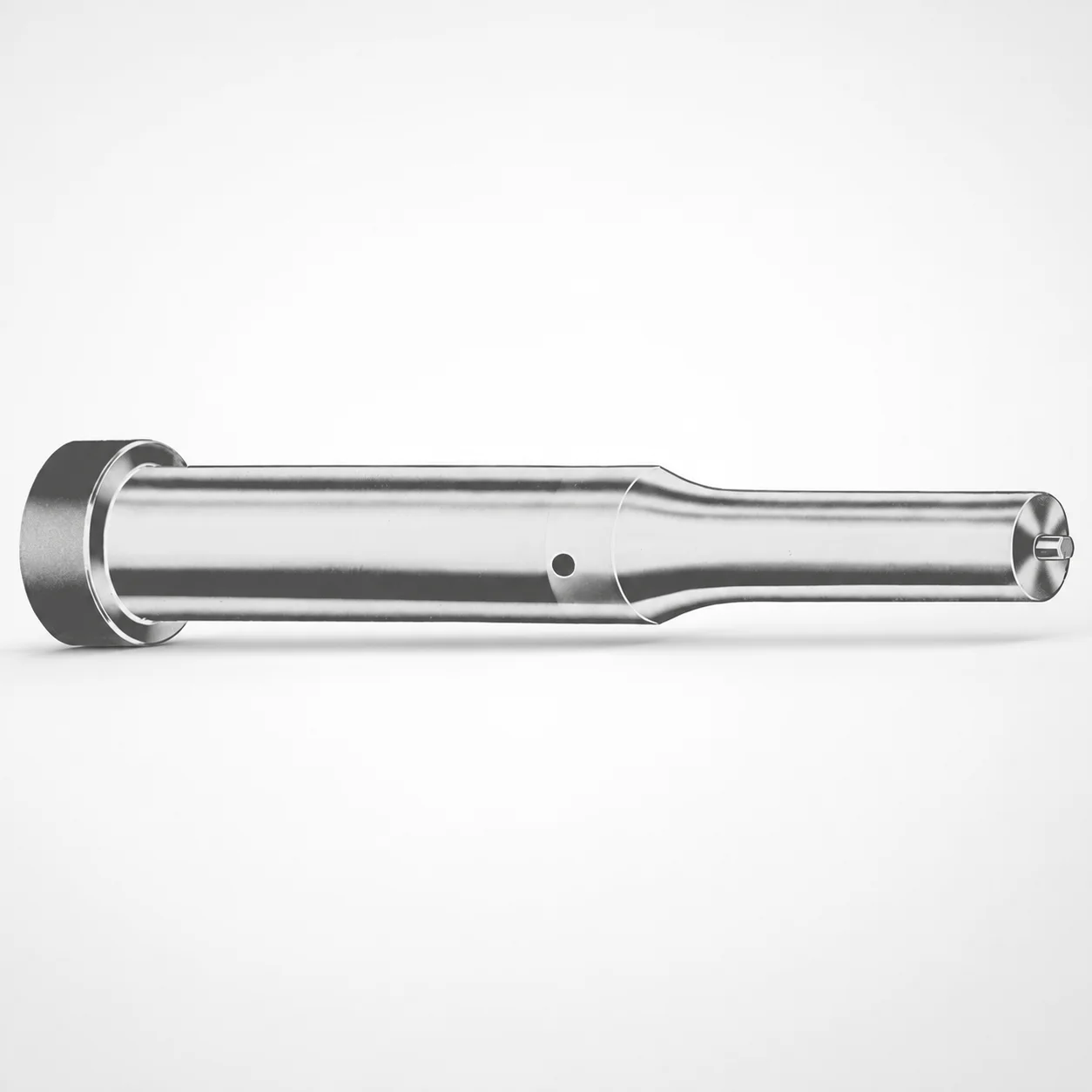
Metric Ejector Punches with X Tip
Metric ejector punches with X tip (Dayton) deliver stable guidance for die and mold ejection, helping achieve consistent punch repeatability in production. The X-shaped point supports controlled contact for reliable operation.
- X-tip geometry for consistent guidance during punch impact
- Dayton LAMINA standardized part format for easier selection
- Manufactured to tight tolerances suitable for die-set assembly
- Commonly used in metric progressive tooling and die ejection systems
Specifications
571 configurations available
| Tip shape | Material | D (Shank dia.) (mm) | Jektole group | L1 (Point Length) (mm) | L (Length) (mm) | P Dimension (mm) | W Dimension (mm) | R Dimension (mm) |
|---|---|---|---|---|---|---|---|---|
| H | M2 | 05 | J2M | 13 ~ 19 | 40 ~ 80 | 1.6 ~ 4.95 | 1.6 ~ 4.95 | - |
| H | A2 | 05 | J2M | 13 ~ 19 | 40 ~ 80 | 1.6 ~ 4.95 | 1.6 ~ 4.95 | - |
| H | PS | 05 | J2M | 13 ~ 19 | 40 ~ 80 | 1.6 ~ 4.95 | 1.6 ~ 4.95 | - |
| H | M2 | 06 | J3M | 13 ~ 19 | 40 ~ 100 | 2 ~ 5.95 | 2 ~ 2.39 | - |
| H | M2 | 06 | J3M | 13 ~ 19 | 40 ~ 100 | 2 ~ 5.95 | 2.4 ~ 5.95 | - |
| H | A2 | 06 | J3M | 13 ~ 19 | 40 ~ 100 | 2 ~ 5.95 | 2 ~ 2.39 | - |
| H | A2 | 06 | J3M | 13 ~ 19 | 40 ~ 100 | 2 ~ 5.95 | 2.4 ~ 5.95 | - |
| H | PS | 06 | J3M | 13 ~ 19 | 40 ~ 100 | 2 ~ 5.95 | 2 ~ 2.39 | - |
| H | PS | 06 | J3M | 13 ~ 19 | 40 ~ 100 | 2 ~ 5.95 | 2.4 ~ 5.95 | - |
| H | M2 | 08 | J4M | 19 ~ 25 | 50 ~ 100 | 3 ~ 7.95 | 3 ~ 3.19 | - |
| H | M2 | 08 | J4M | 19 ~ 25 | 50 ~ 100 | 3 ~ 7.95 | 3.2 ~ 7.95 | - |
| H | A2 | 08 | J4M | 19 ~ 25 | 50 ~ 100 | 3 ~ 7.95 | 3 ~ 3.19 | - |
| H | A2 | 08 | J4M | 19 ~ 25 | 50 ~ 100 | 3 ~ 7.95 | 3.2 ~ 7.95 | - |
| H | PS | 08 | J4M | 19 ~ 25 | 50 ~ 100 | 3 ~ 7.95 | 3 ~ 3.19 | - |
| H | PS | 08 | J4M | 19 ~ 25 | 50 ~ 100 | 3 ~ 7.95 | 3.2 ~ 7.95 | - |
| H | M2 | 10 | J6M | 19 ~ 25 | 50 ~ 100 | 4 ~ 9.95 | 4 ~ 4.49 | - |
| H | M2 | 10 | J6M | 19 ~ 25 | 50 ~ 100 | 4 ~ 9.95 | 4.5 ~ 9.95 | - |
| H | A2 | 10 | J6M | 19 ~ 25 | 50 ~ 100 | 4 ~ 9.95 | 4 ~ 4.49 | - |
| H | A2 | 10 | J6M | 19 ~ 25 | 50 ~ 100 | 4 ~ 9.95 | 4.5 ~ 9.95 | - |
| H | PS | 10 | J6M | 19 ~ 25 | 50 ~ 100 | 4 ~ 9.95 | 4 ~ 4.49 | - |
| H | PS | 10 | J6M | 19 ~ 25 | 50 ~ 100 | 4 ~ 9.95 | 4.5 ~ 9.95 | - |
| H | M2 | 13 | J6M | 19 ~ 25 | 50 ~ 100 | 4 ~ 12.95 | 4 ~ 5.99 | - |
| H | M2 | 13 | J6M | 19 ~ 25 | 50 ~ 100 | 4 ~ 12.95 | 6 ~ 12.95 | - |
| H | A2 | 13 | J6M | 19 ~ 25 | 50 ~ 100 | 4 ~ 12.95 | 4 ~ 5.99 | - |
| H | A2 | 13 | J6M | 19 ~ 25 | 50 ~ 100 | 4 ~ 12.95 | 6 ~ 12.95 | - |
| H | PS | 13 | J6M | 19 ~ 25 | 50 ~ 100 | 4 ~ 12.95 | 4 ~ 5.99 | - |
| H | PS | 13 | J6M | 19 ~ 25 | 50 ~ 100 | 4 ~ 12.95 | 6 ~ 12.95 | - |
| H | M2 | 16 | J9M | 19 ~ 25 | 50 ~ 100 | 6 ~ 15.95 | 6 ~ 7.19 | - |
| H | M2 | 16 | J9M | 19 ~ 25 | 50 ~ 100 | 6 ~ 15.95 | 7.2 ~ 15.95 | - |
| H | A2 | 16 | J9M | 19 ~ 25 | 50 ~ 100 | 6 ~ 15.95 | 6 ~ 7.19 | - |
| H | A2 | 16 | J9M | 19 ~ 25 | 50 ~ 100 | 6 ~ 15.95 | 7.2 ~ 15.95 | - |
| H | PS | 16 | J9M | 19 ~ 25 | 50 ~ 100 | 6 ~ 15.95 | 6 ~ 7.19 | - |
| H | PS | 16 | J9M | 19 ~ 25 | 50 ~ 100 | 6 ~ 15.95 | 7.2 ~ 15.95 | - |
| H | M2 | 20 | J9M | 19 ~ 25 | 50 ~ 100 | 6 ~ 19.95 | 6 ~ 7.99 | - |
| H | M2 | 20 | J9M | 19 ~ 25 | 50 ~ 100 | 6 ~ 19.95 | 8 ~ 19.95 | - |
| H | A2 | 20 | J9M | 19 ~ 25 | 50 ~ 100 | 6 ~ 19.95 | 6 ~ 7.99 | - |
| H | A2 | 20 | J9M | 19 ~ 25 | 50 ~ 100 | 6 ~ 19.95 | 8 ~ 19.95 | - |
| H | PS | 20 | J9M | 19 ~ 25 | 50 ~ 100 | 6 ~ 19.95 | 6 ~ 7.99 | - |
| H | PS | 20 | J9M | 19 ~ 25 | 50 ~ 100 | 6 ~ 19.95 | 8 ~ 19.95 | - |
| H | M2 | 25 | J9M | 19 ~ 25 | 50 ~ 100 | 6 ~ 24.95 | 6 ~ 8.99 | - |
| H | M2 | 25 | J9M | 19 ~ 25 | 50 ~ 100 | 6 ~ 24.95 | 9 ~ 24.95 | - |
| H | A2 | 25 | J9M | 19 ~ 25 | 50 ~ 100 | 6 ~ 24.95 | 6 ~ 8.99 | - |
| H | A2 | 25 | J9M | 19 ~ 25 | 50 ~ 100 | 6 ~ 24.95 | 9 ~ 24.95 | - |
| H | PS | 25 | J9M | 19 ~ 25 | 50 ~ 100 | 6 ~ 24.95 | 6 ~ 8.99 | - |
| H | PS | 25 | J9M | 19 ~ 25 | 50 ~ 100 | 6 ~ 24.95 | 9 ~ 24.95 | - |
| H | M2 | 32 | J12M | 25 ~ 30 | 63 ~ 100 | 7.2 ~ 31.95 | 7.2 ~ 9.99 | - |
| H | M2 | 32 | J12M | 25 ~ 30 | 63 ~ 100 | 7.2 ~ 31.95 | 10 ~ 31.95 | - |
| H | A2 | 32 | J12M | 25 ~ 30 | 63 ~ 100 | 7.2 ~ 31.95 | 7.2 ~ 9.99 | - |
| H | A2 | 32 | J12M | 25 ~ 30 | 63 ~ 100 | 7.2 ~ 31.95 | 10 ~ 31.95 | - |
| H | PS | 32 | J12M | 25 ~ 30 | 63 ~ 100 | 7.2 ~ 31.95 | 7.2 ~ 9.99 | - |
Product Guide
Application Scenarios+
Precision die and mold ejection guidance: These metric ejector punches with an X tip are used in progressive die tooling and transfer stations where the punch must enter and retract smoothly for consistent part release. The X-shaped point supports controlled contact, improving guidance during punch impact and reducing misalignment risk over high cycle counts.
- Automotive and appliance progressive tooling: In die sets with frequent ejector actuation, the standardized punch format helps match existing assembly layouts while maintaining repeatable positioning across production lines.
- Sheet metal forming dies: When ejection depends on stable punch penetration and clean withdrawal, the X tip geometry provides reliable contact characteristics for improved die-set performance.
- High-mix production runs: Engineers can select from multiple tip shapes (including X) and shank diameters (5–32 mm) to fit different cavity/core footprints and ejection strokes.
Why this variant fits: The X tip option is suited when controlled guidance at the point is critical to consistent ejection, and the metric standardized format supports easier selection for die-set integration.
Material & Process Details+
Available materials for these metric ejector punches include M2, A2, and PS, selected to balance wear resistance, toughness, and manufacturing approach for different die environments. In hardened tooling applications, M2 is typically used where higher hardness and wear resistance are needed, while A2 is commonly chosen for strong toughness with good wear behavior.
- M2: High-speed steel family; generally offers excellent wear resistance with a hardness commonly around HRC ~ 60–62 after appropriate heat treatment.
- A2: Air-hardening tool steel; commonly hardened to HRC ~ 55–60, with a toughness/wear trade-off vs. very high wear grades.
- PS: Often selected when a specific performance/production requirement is prioritized; exact hardness and heat treatment state should be confirmed for your selected group.
Manufacturing and heat treatment: After machining to shank diameter (D) and length (L/L1), components are heat treated and then ground/finished to maintain guidance and fit in the die-set ejector system. Final hardness supports wear resistance at the point while controlling chipping risk under repeated impact.
Sizing & Selection Guide+
Correct sizing starts with matching the shank diameter (D) and the overall geometry to your die-set ejector guide and pocket. Select D = 5–32 mm based on the ejector bushing/guide system bore that the punch will run in.
- Point length (L1): Choose from 13–19 mm, 19–25 mm, or 25–30 mm to control how far the point extends into the work area.
- Total length (L): Options include 40–80 mm, 40–100 mm, 50–100 mm, or 63–100 mm, matched to your stroke clearance and guide engagement depth.
- Cross dimensions: Use P = 1.3–16 mm, W = 1.6–10 mm, and radius R = 0.2 mm to ensure the point profile is compatible with the die cavity/core clearance.
Tolerance and fit: Because the punch provides guidance during impact, maintain consistent fit with the mating guide/bushing to limit side load. If multiple length ranges exist for the same D, prefer the shortest L that still achieves required engagement and ejection travel, while preserving clearance for the X tip during return.
Frequently Asked Questions
Which dimensions control the guidance performance for an ejector punch with an X tip?+
The primary controls are D (shank diameter, 5–32 mm) for guide fit, and the point geometry defined by the selected tip shape (X) and L1 (point length: 13–19, 19–25, or 25–30 mm).
Use the overall length (L) (e.g., 40–80, 40–100, 50–100, 63–100 mm) to ensure correct engagement without excessive protrusion during impact.
How do I choose between the available L and L1 ranges for correct ejection stroke clearance?+
Match L to the required ejector stroke and the available guide engagement in your die-set. Then set L1 so the X tip reaches the intended contact depth into the die area without interfering with cavity/core features during retraction.
If your system has multiple die heights, prefer the L range that maintains the same clearance margin while minimizing unnecessary over-travel.
What material should I select (M2 vs A2 vs PS) for wear and impact resistance in punch ejection systems?+
Material choice affects wear resistance and toughness. M2 is commonly selected when higher wear resistance is required (typically hardened to around HRC ~ 60–62 after heat treatment), while A2 is often chosen for a strong toughness/wear balance (commonly around HRC ~ 55–60).
PS may be used when a specific performance requirement is defined by the Jektole group; confirm the exact hardness/heat treatment state for your selected variant.
Can I substitute another tip shape (H, J, K, L, N, O, R, V, X, Y, Z) in the same series without redesigning the guide?+
Tip shape substitution can be feasible for guidance and ejection contact, but it impacts the contact profile and may require checking clearance around the cavity/core.
To avoid redesign of the guide, keep D constant and re-verify compatibility using L1, P (1.3–16 mm), W (1.6–10 mm), and the fixed radius R = 0.2 mm.
What are the key sizing checks for mating this punch to die-set ejector components?+
Verify the mating guide/bushing bore against D (5–32 mm) to ensure correct fit and stable guidance during impact. Then confirm that the point and body dimensions—L1, L, and profile parameters P, W, and R—fit within the cavity/core clearance envelope.
Because the punch is used for repeatable positioning in production tooling, maintain consistent tolerance stack-up between the punch and guide components.
Related Products






Need Custom Specifications?
Our engineering team can help with custom configurations, material selection, and volume pricing.