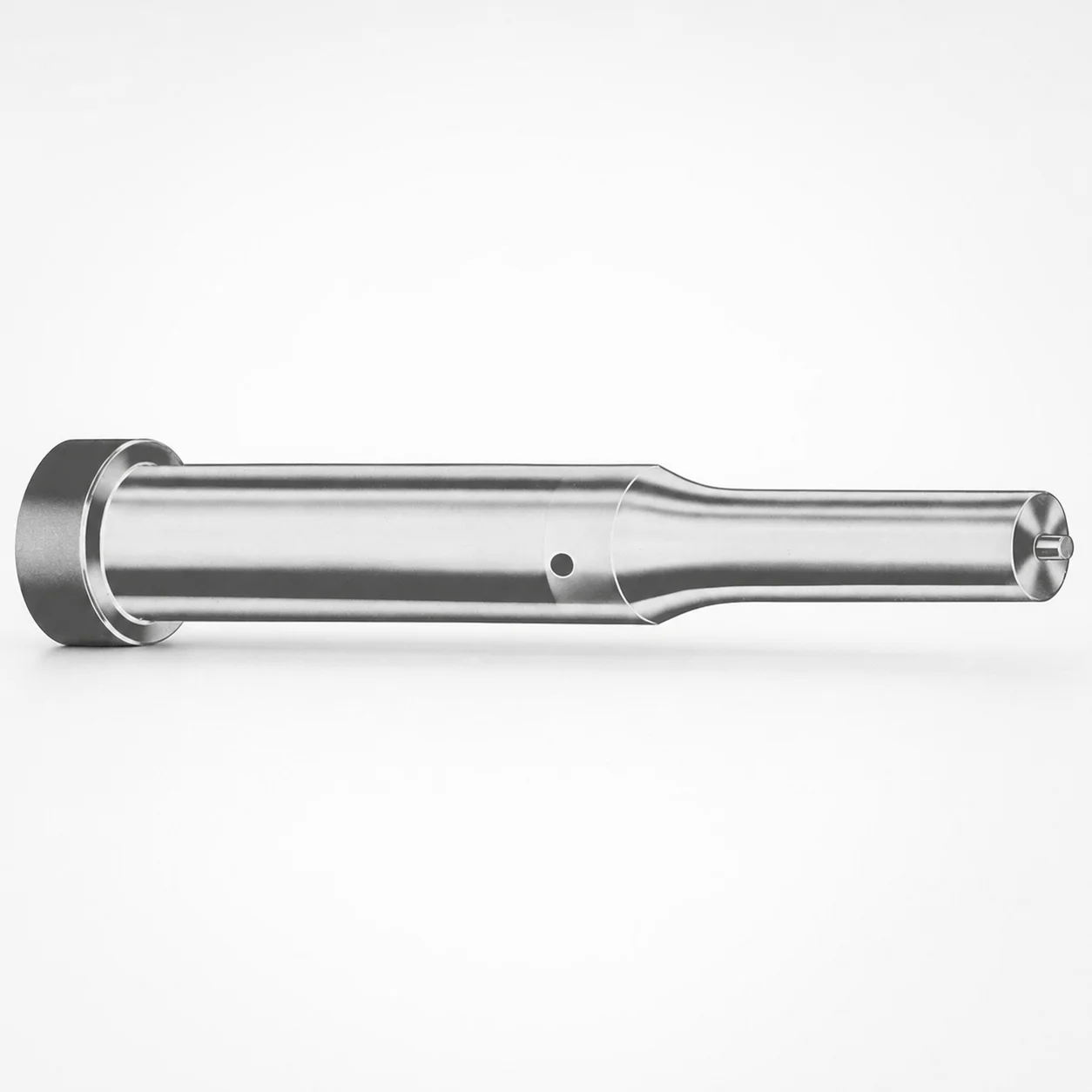
CRN Coated Metric Ejector Punches with X Tip
Metric ejector punches with CRN coating and an X tip are designed for reliable part removal in close-clearance mold cavities. The coated punch body supports stable surface performance under repeated cycles.
- X tip geometry improves engagement for controlled ejector contact
- CRN coating helps reduce wear during high-frequency molding operations
- Standardized metric punch construction supports accurate die-ready setup
- Suitable for progressive forming and injection molding tooling applications
Specifications
367 configurations available
| Tip shape | Material | D (Shank dia.) (mm) | Jektole group | L1 (Point Length) (mm) | L (Length) (mm) | P Dimension (mm) | W Dimension (mm) | R Dimension (mm) |
|---|---|---|---|---|---|---|---|---|
| H | M2 | 05 | J2M | 13 ~ 19 | 40 ~ 80 | 1.6 ~ 4.95 | 1.6 ~ 4.95 | - |
| H | PS | 05 | J2M | 13 ~ 19 | 40 ~ 80 | 1.6 ~ 4.95 | 1.6 ~ 4.95 | - |
| H | M2 | 06 | J3M | 13 ~ 19 | 40 ~ 100 | 2 ~ 5.95 | 2 ~ 2.39 | - |
| H | M2 | 06 | J3M | 13 ~ 19 | 40 ~ 100 | 2 ~ 5.95 | 2.4 ~ 5.95 | - |
| H | PS | 06 | J3M | 13 ~ 19 | 40 ~ 100 | 2 ~ 5.95 | 2 ~ 2.39 | - |
| H | PS | 06 | J3M | 13 ~ 19 | 40 ~ 100 | 2 ~ 5.95 | 2.4 ~ 5.95 | - |
| H | M2 | 08 | J4M | 19 ~ 25 | 50 ~ 100 | 3 ~ 7.95 | 3 ~ 3.19 | - |
| H | M2 | 08 | J4M | 19 ~ 25 | 50 ~ 100 | 3 ~ 7.95 | 3.2 ~ 7.95 | - |
| H | PS | 08 | J4M | 19 ~ 25 | 50 ~ 100 | 3 ~ 7.95 | 3 ~ 3.19 | - |
| H | PS | 08 | J4M | 19 ~ 25 | 50 ~ 100 | 3 ~ 7.95 | 3.2 ~ 7.95 | - |
| H | M2 | 10 | J6M | 19 ~ 25 | 50 ~ 100 | 4 ~ 9.95 | 4 ~ 4.49 | - |
| H | M2 | 10 | J6M | 19 ~ 25 | 50 ~ 100 | 4 ~ 9.95 | 4.5 ~ 9.95 | - |
| H | PS | 10 | J6M | 19 ~ 25 | 50 ~ 100 | 4 ~ 9.95 | 4 ~ 4.49 | - |
| H | PS | 10 | J6M | 19 ~ 25 | 50 ~ 100 | 4 ~ 9.95 | 4.5 ~ 9.95 | - |
| H | M2 | 13 | J6M | 19 ~ 25 | 50 ~ 100 | 4 ~ 12.95 | 4 ~ 5.99 | - |
| H | M2 | 13 | J6M | 19 ~ 25 | 50 ~ 100 | 4 ~ 12.95 | 6 ~ 12.95 | - |
| H | PS | 13 | J6M | 19 ~ 25 | 50 ~ 100 | 4 ~ 12.95 | 4 ~ 5.99 | - |
| H | PS | 13 | J6M | 19 ~ 25 | 50 ~ 100 | 4 ~ 12.95 | 6 ~ 12.95 | - |
| H | M2 | 16 | J9M | 19 ~ 25 | 50 ~ 100 | 6 ~ 15.95 | 6 ~ 7.19 | - |
| H | M2 | 16 | J9M | 19 ~ 25 | 50 ~ 100 | 6 ~ 15.95 | 7.2 ~ 15.95 | - |
| H | PS | 16 | J9M | 19 ~ 25 | 50 ~ 100 | 6 ~ 15.95 | 6 ~ 7.19 | - |
| H | PS | 16 | J9M | 19 ~ 25 | 50 ~ 100 | 6 ~ 15.95 | 7.2 ~ 15.95 | - |
| H | M2 | 20 | J9M | 19 ~ 25 | 50 ~ 100 | 6 ~ 19.95 | 6 ~ 7.99 | - |
| H | M2 | 20 | J9M | 19 ~ 25 | 50 ~ 100 | 6 ~ 19.95 | 8 ~ 19.95 | - |
| H | PS | 20 | J9M | 19 ~ 25 | 50 ~ 100 | 6 ~ 19.95 | 6 ~ 7.99 | - |
| H | PS | 20 | J9M | 19 ~ 25 | 50 ~ 100 | 6 ~ 19.95 | 8 ~ 19.95 | - |
| H | M2 | 25 | J9M | 19 ~ 25 | 50 ~ 100 | 6 ~ 24.95 | 6 ~ 8.99 | - |
| H | M2 | 25 | J9M | 19 ~ 25 | 50 ~ 100 | 6 ~ 24.95 | 9 ~ 24.95 | - |
| H | PS | 25 | J9M | 19 ~ 25 | 50 ~ 100 | 6 ~ 24.95 | 6 ~ 8.99 | - |
| H | PS | 25 | J9M | 19 ~ 25 | 50 ~ 100 | 6 ~ 24.95 | 9 ~ 24.95 | - |
| H | M2 | 32 | J12M | 25 ~ 30 | 63 ~ 100 | 7.2 ~ 31.95 | 7.2 ~ 9.99 | - |
| H | M2 | 32 | J12M | 25 ~ 30 | 63 ~ 100 | 7.2 ~ 31.95 | 10 ~ 31.95 | - |
| H | PS | 32 | J12M | 25 ~ 30 | 63 ~ 100 | 7.2 ~ 31.95 | 7.2 ~ 9.99 | - |
| H | PS | 32 | J12M | 25 ~ 30 | 63 ~ 100 | 7.2 ~ 31.95 | 10 ~ 31.95 | - |
| J | M2 | 05 | J2M | 13 ~ 19 | 40 ~ 80 | 1.6 ~ 4.95 | 1.6 ~ 4.95 | - |
| J | PS | 05 | J2M | 13 ~ 19 | 40 ~ 80 | 1.6 ~ 4.95 | 1.6 ~ 4.95 | - |
| J | M2 | 06 | J3M | 13 ~ 19 | 40 ~ 100 | 2 ~ 5.95 | 2 ~ 2.39 | - |
| J | M2 | 06 | J3M | 13 ~ 19 | 40 ~ 100 | 2 ~ 5.95 | 2.4 ~ 5.95 | - |
| J | PS | 06 | J3M | 13 ~ 19 | 40 ~ 100 | 2 ~ 5.95 | 2 ~ 2.39 | - |
| J | PS | 06 | J3M | 13 ~ 19 | 40 ~ 100 | 2 ~ 5.95 | 2.4 ~ 5.95 | - |
| J | M2 | 08 | J4M | 19 ~ 25 | 50 ~ 100 | 3 ~ 7.95 | 3 ~ 3.19 | - |
| J | M2 | 08 | J4M | 19 ~ 25 | 50 ~ 100 | 3 ~ 7.95 | 3.2 ~ 7.95 | - |
| J | PS | 08 | J4M | 19 ~ 25 | 50 ~ 100 | 3 ~ 7.95 | 3 ~ 3.19 | - |
| J | PS | 08 | J4M | 19 ~ 25 | 50 ~ 100 | 3 ~ 7.95 | 3.2 ~ 7.95 | - |
| J | M2 | 10 | J6M | 19 ~ 25 | 50 ~ 100 | 4 ~ 9.95 | 4 ~ 4.49 | - |
| J | M2 | 10 | J6M | 19 ~ 25 | 50 ~ 100 | 4 ~ 9.95 | 4.5 ~ 9.95 | - |
| J | PS | 10 | J6M | 19 ~ 25 | 50 ~ 100 | 4 ~ 9.95 | 4 ~ 4.49 | - |
| J | PS | 10 | J6M | 19 ~ 25 | 50 ~ 100 | 4 ~ 9.95 | 4.5 ~ 9.95 | - |
| J | M2 | 13 | J6M | 19 ~ 25 | 50 ~ 100 | 4 ~ 12.95 | 4 ~ 5.99 | - |
| J | M2 | 13 | J6M | 19 ~ 25 | 50 ~ 100 | 4 ~ 12.95 | 6 ~ 12.95 | - |
Product Guide
Application Scenarios+
These metric ejector punches are used in injection molding tooling and forming dies where consistent part ejection is required in tight, close-clearance cavities. The X tip geometry is specifically suited for controlled contact with molded parts and ejector wear-sensitive surfaces, helping maintain repeatable ejection forces over long runs.
- Automotive and appliance housings: eingesetzt in multi-up or high-cycle molds to support stable ejection when features require minimal clearance between punch and cavity wall.
- Medical device housings and caps: used for precision removal of small components where surface finish matters; the CRN coating helps reduce wear from repeated rubbing and sliding.
- Progressive forming / insert molds: compatible with tool systems that benefit from standardized metric punch construction for faster die-ready setup and consistent fit across cavities.
Choose this variant when you need close-clearance ejection with enhanced surface durability from CRN, while relying on the X tip for controlled engagement at the contact interface.
Material & Process Details+
This ejector punch is available in M2 and PS steel grades, paired with a CRN coating for improved surface performance under high-frequency cycling. M2 is a high-speed tool steel commonly selected for its strong wear resistance and good hot-work capability; with typical quench-and-temper processing, it offers a balanced toughness vs. hardness trade-off for punching and ejector applications.
PS steel is generally chosen when robustness and cost-effective tooling performance are priorities for standardized ejector systems. The CRN layer increases abrasion resistance and reduces metal-to-metal wear during repeated ejector strokes.
- Wear resistance: improved by CRN coating on both M2 and PS.
- Toughness trade-off: harder tool-steel selections (commonly associated with M2) can reduce wear but may require careful fit to avoid chipping in very tight geometries.
Heat treatment should be selected to match the chosen grade and target hardness; final hardness and exact treatment state are typically defined by the toolmaker per the steel grade used.
Sizing & Selection Guide+
Select ejector punch size by matching the shank diameter (D), overall length (L), and point length (L1) to the die/core and available stroke space. This series provides D = 5–32 mm, with multiple options for L1 = 13–19 mm, 19–25 mm, and 25–30 mm. Overall L is offered in ranges such as 40–80 mm, 40–100 mm, 50–100 mm, and 63–100 mm.
- Core/cavity engagement: use the X tip with the correct L1 to ensure the desired contact length without bottoming in the guide.
- Clearance control: in close-clearance cavities, verify the P (1.3–16 mm) and W (1.6–10 mm) dimensions are compatible with the part geometry and surrounding clearance features.
- Guide fit: select a D that matches the ejector pin bore/guide system; plan for machining and assembly tolerances to prevent binding or excessive lateral play.
Where multiple ranges are available, choose the smallest L that still allows full stroke and safe retention, while ensuring the L1 supports consistent ejection contact.
Frequently Asked Questions
How do I choose the correct X tip variant for close-clearance ejector contact?+
What dimensions matter most to prevent ejector binding in guide systems?+
Which steel grade is more suitable: M2 or PS, when CRN coating is used?+
How do point length L1 and overall length L work together in ejector design?+
Do the P, W, and R dimensions affect die-ready compatibility for progressive forming and injection tools?+
Related Products






Need Custom Specifications?
Our engineering team can help with custom configurations, material selection, and volume pricing.