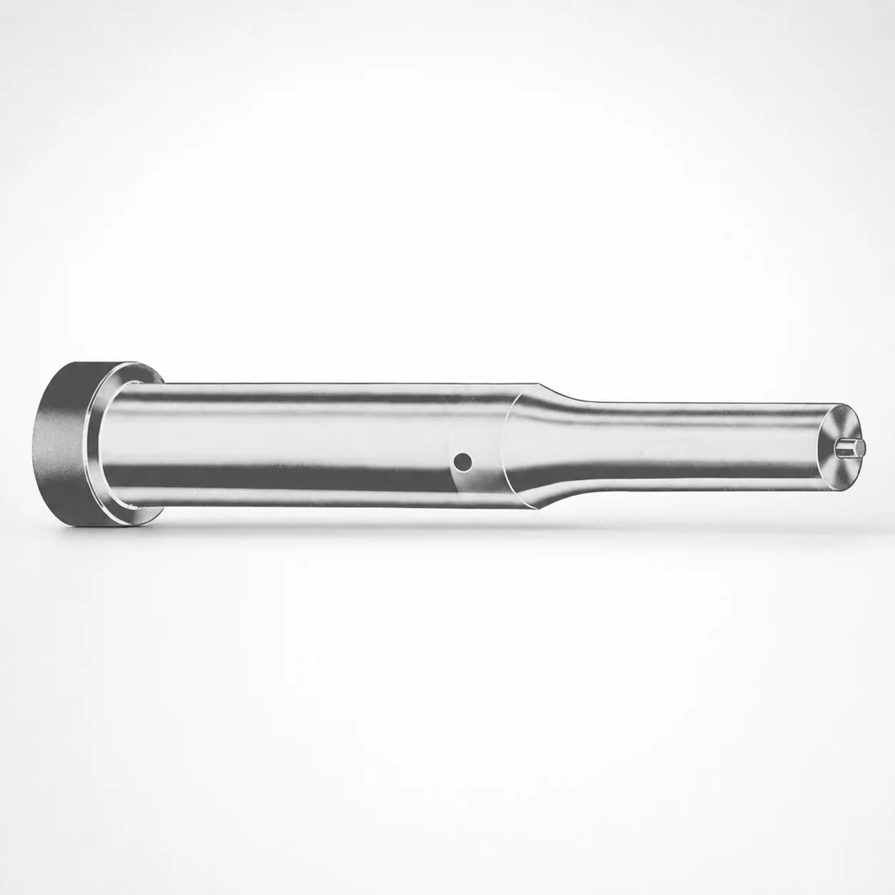
Inch Ejector Punches
Ejector Punches (Inch series) are precision punch components designed for consistent part ejection in stamping and die applications. DAYTON manufacturing supports stable fit and dependable punching performance across production runs.
- Inch punch design for efficient operation in standard tooling setups
- Available in M2 and A2 steel for durable wear resistance
- Built for repeatable assembly with controlled point length coding
- Suitable for punching tasks in mechanical presses and mold tooling
Specifications
1506 configurations available
| Tip shape | Material | D (Shank dia.) (in) | Jektole group | Standard [S] Point Length B & L (Length) (coded inch) | Alternate [B] Point Length B & L (Length) (coded inch) | Alternate [C] Point Length B & L (Length) (coded inch) | Alternate [D] Point Length B & L (Length) (coded inch) | Alternate [E] Point Length B & L (Length) (coded inch) | P Dimension (in) | W Dimension (in) | R Dimension (in) |
|---|---|---|---|---|---|---|---|---|---|---|---|
| H | M2 | 18(0.1875") | J2 | - | 150 ~ 400 | - | - | - | 0.062 ~ 0.1875 | 0.062 ~ 0.1875 | - |
| H | A2 | 18(0.1875") | J2 | - | 150 ~ 400 | - | - | - | 0.062 ~ 0.1875 | 0.062 ~ 0.1875 | - |
| H | M2 | 18(0.1875") | J2 | 150 ~ 400 | - | - | - | - | 0.062 ~ 0.1875 | 0.062 ~ 0.1875 | - |
| H | A2 | 18(0.1875") | J2 | 150 ~ 400 | - | - | - | - | 0.062 ~ 0.1875 | 0.062 ~ 0.1875 | - |
| H | M2 | 25(0.2500") | J3 | - | 150 ~ 400 | - | - | - | 0.08 ~ 0.25 | 0.08 ~ 0.0929 | - |
| H | M2 | 25(0.2500") | J3 | - | 150 ~ 400 | - | - | - | 0.08 ~ 0.25 | 0.093 ~ 0.25 | - |
| H | A2 | 25(0.2500") | J3 | - | 150 ~ 400 | - | - | - | 0.08 ~ 0.25 | 0.08 ~ 0.0929 | - |
| H | A2 | 25(0.2500") | J3 | - | 150 ~ 400 | - | - | - | 0.08 ~ 0.25 | 0.093 ~ 0.25 | - |
| H | M2 | 25(0.2500") | J3 | 150 ~ 400 | - | - | - | - | 0.08 ~ 0.25 | 0.08 ~ 0.0929 | - |
| H | M2 | 25(0.2500") | J3 | 150 ~ 400 | - | - | - | - | 0.08 ~ 0.25 | 0.093 ~ 0.25 | - |
| H | A2 | 25(0.2500") | J3 | 150 ~ 400 | - | - | - | - | 0.08 ~ 0.25 | 0.08 ~ 0.0929 | - |
| H | A2 | 25(0.2500") | J3 | 150 ~ 400 | - | - | - | - | 0.08 ~ 0.25 | 0.093 ~ 0.25 | - |
| H | M2 | 31(0.3125") | J4 | - | 150 ~ 600 | - | - | - | 0.115 ~ 0.3125 | 0.115 ~ 0.1249 | - |
| H | M2 | 31(0.3125") | J4 | - | 150 ~ 600 | - | - | - | 0.115 ~ 0.3125 | 0.125 ~ 0.3125 | - |
| H | A2 | 31(0.3125") | J4 | - | 150 ~ 600 | - | - | - | 0.115 ~ 0.3125 | 0.115 ~ 0.1249 | - |
| H | A2 | 31(0.3125") | J4 | - | 150 ~ 600 | - | - | - | 0.115 ~ 0.3125 | 0.125 ~ 0.3125 | - |
| H | M2 | 31(0.3125") | J4 | - | - | 175 ~ 600 | - | - | 0.115 ~ 0.3125 | 0.115 ~ 0.1249 | - |
| H | M2 | 31(0.3125") | J4 | - | - | 175 ~ 600 | - | - | 0.115 ~ 0.3125 | 0.125 ~ 0.3125 | - |
| H | A2 | 31(0.3125") | J4 | - | - | 175 ~ 600 | - | - | 0.115 ~ 0.3125 | 0.115 ~ 0.1249 | - |
| H | A2 | 31(0.3125") | J4 | - | - | 175 ~ 600 | - | - | 0.115 ~ 0.3125 | 0.125 ~ 0.3125 | - |
| H | M2 | 31(0.3125") | J4 | 150 ~ 600 | - | - | - | - | 0.115 ~ 0.3125 | 0.115 ~ 0.1249 | - |
| H | M2 | 31(0.3125") | J4 | 150 ~ 600 | - | - | - | - | 0.115 ~ 0.3125 | 0.125 ~ 0.3125 | - |
| H | A2 | 31(0.3125") | J4 | 150 ~ 600 | - | - | - | - | 0.115 ~ 0.3125 | 0.115 ~ 0.1249 | - |
| H | A2 | 31(0.3125") | J4 | 150 ~ 600 | - | - | - | - | 0.115 ~ 0.3125 | 0.125 ~ 0.3125 | - |
| H | M2 | 37(0.3750") | J6 | - | 175 ~ 625 | - | - | - | 0.158 ~ 0.375 | 0.158 ~ 0.1869 | - |
| H | M2 | 37(0.3750") | J6 | - | 175 ~ 625 | - | - | - | 0.158 ~ 0.375 | 0.187 ~ 0.375 | - |
| H | A2 | 37(0.3750") | J6 | - | 175 ~ 625 | - | - | - | 0.158 ~ 0.375 | 0.158 ~ 0.1869 | - |
| H | A2 | 37(0.3750") | J6 | - | 175 ~ 625 | - | - | - | 0.158 ~ 0.375 | 0.187 ~ 0.375 | - |
| H | M2 | 37(0.3750") | J6 | - | - | 175 ~ 625 | - | - | 0.158 ~ 0.375 | 0.158 ~ 0.1869 | - |
| H | M2 | 37(0.3750") | J6 | - | - | 175 ~ 625 | - | - | 0.158 ~ 0.375 | 0.187 ~ 0.375 | - |
| H | A2 | 37(0.3750") | J6 | - | - | 175 ~ 625 | - | - | 0.158 ~ 0.375 | 0.158 ~ 0.1869 | - |
| H | A2 | 37(0.3750") | J6 | - | - | 175 ~ 625 | - | - | 0.158 ~ 0.375 | 0.187 ~ 0.375 | - |
| H | M2 | 37(0.3750") | J6 | 175 ~ 625 | - | - | - | - | 0.158 ~ 0.375 | 0.158 ~ 0.1869 | - |
| H | M2 | 37(0.3750") | J6 | 175 ~ 625 | - | - | - | - | 0.158 ~ 0.375 | 0.187 ~ 0.375 | - |
| H | A2 | 37(0.3750") | J6 | 175 ~ 625 | - | - | - | - | 0.158 ~ 0.375 | 0.158 ~ 0.1869 | - |
| H | A2 | 37(0.3750") | J6 | 175 ~ 625 | - | - | - | - | 0.158 ~ 0.375 | 0.187 ~ 0.375 | - |
| H | M2 | 43(0.4375") | J6 | - | - | 200 ~ 625 | - | - | 0.158 ~ 0.4375 | 0.158 ~ 0.1869 | - |
| H | M2 | 43(0.4375") | J6 | - | - | 200 ~ 625 | - | - | 0.158 ~ 0.4375 | 0.187 ~ 0.4375 | - |
| H | A2 | 43(0.4375") | J6 | - | - | 200 ~ 625 | - | - | 0.158 ~ 0.4375 | 0.158 ~ 0.1869 | - |
| H | A2 | 43(0.4375") | J6 | - | - | 200 ~ 625 | - | - | 0.158 ~ 0.4375 | 0.187 ~ 0.4375 | - |
| H | M2 | 43(0.4375") | J6 | 200 ~ 625 | - | - | - | - | 0.158 ~ 0.4375 | 0.158 ~ 0.1869 | - |
| H | M2 | 43(0.4375") | J6 | 200 ~ 625 | - | - | - | - | 0.158 ~ 0.4375 | 0.187 ~ 0.4375 | - |
| H | A2 | 43(0.4375") | J6 | 200 ~ 625 | - | - | - | - | 0.158 ~ 0.4375 | 0.158 ~ 0.1869 | - |
| H | A2 | 43(0.4375") | J6 | 200 ~ 625 | - | - | - | - | 0.158 ~ 0.4375 | 0.187 ~ 0.4375 | - |
| H | M2 | 50(0.5000") | J6 | - | - | 200 ~ 625 | - | - | 0.158 ~ 0.5 | 0.158 ~ 0.1869 | - |
| H | M2 | 50(0.5000") | J6 | - | - | 200 ~ 625 | - | - | 0.158 ~ 0.5 | 0.187 ~ 0.5 | - |
| H | A2 | 50(0.5000") | J6 | - | - | 200 ~ 625 | - | - | 0.158 ~ 0.5 | 0.158 ~ 0.1869 | - |
| H | A2 | 50(0.5000") | J6 | - | - | 200 ~ 625 | - | - | 0.158 ~ 0.5 | 0.187 ~ 0.5 | - |
| H | M2 | 50(0.5000") | J6 | 200 ~ 625 | - | - | - | - | 0.158 ~ 0.5 | 0.158 ~ 0.1869 | - |
| H | M2 | 50(0.5000") | J6 | 200 ~ 625 | - | - | - | - | 0.158 ~ 0.5 | 0.187 ~ 0.5 | - |
Product Guide
Application Scenarios+
In injection and die tooling, these inch ejector punches are used to drive ejection action reliably after molding or forming. They are typically installed in stripper plates or ejector systems where consistent point geometry is needed to push molded parts off the cavity without distortion.
They fit well in die casting and press tool applications where repeated punching/stripping cycles demand wear-resistant punch tips; choosing M2 or A2 supports long service intervals under abrasive wear and cyclic loading.
For multi-cavity or progressive tooling, the coded point length ranges help engineers match required stroke length and maintain uniform ejection across stations.
- Use the appropriate tip shape (H, J, K, L, N, O, R, V, X, Y, Z) to align with part undercuts and ejection forces.
- Select shank diameter D = 18–250 in to maintain stiffness and prevent bending during ejection.
Material & Process Details+
This ejector punch series is offered in M2 and A2 tool steels, selected for toughness-to-wear balance in punching and ejection duty. The steel selection primarily affects wear resistance, tip edge stability, and resistance to micro-chipping under cyclic contact.
- M2 (high-speed steel class) is commonly chosen where higher hot hardness and wear resistance are prioritized; it tends to deliver improved durability in demanding stripping cycles.
- A2 (air-hardening tool steel class) is often selected for good toughness and reliable performance in environments with less extreme heat than pure hot-work conditions.
Heat treatment is typically quenched and tempered for both tool steel options to achieve target hardness and toughness. Hardness and final performance depend on the selected grade and the delivered heat-treatment cycle for the punch point geometry.
Sizing & Selection Guide+
Correct sizing ensures the ejector punch provides stiffness at the shank and the right effective working length at the tip. Start by matching the shank diameter D (in) = 18–250 to the ejector bore/guide system in the tooling plate to avoid excessive clearance or binding.
Next, select the coded point length B & L within the available ranges. Standard options are 150–250 in, while alternate groups provide ranges such as 150–400, 150–600, 175–625, 200–625, 225–625, 225–650, 250–650, and up to 250–700 (depending on the alternate type and group).
- Choose the Jektole group (J2, J3, J4, J6, J9, J12) that corresponds to the required point-length/geometry package.
- Set the P dimension = 0.05–1.625 in and W dimension = 0.062–0.5 in to satisfy the contact area and clearance to surrounding components.
- Use the R dimension = 0.007–0.007 in as the tip curvature constraint when matching to part surface requirements.
Where close fits are required, confirm tool drawing tolerances for ejector bores and ensure the selected D and point length do not create interference during full travel.
Frequently Asked Questions
How do I choose between M2 and A2 steel for ejector punching duty in press and die applications?+
Both options are available for this inch ejector punch series, and the choice is driven by the wear-versus-toughness requirement of your ejection cycle. M2 is typically selected when higher wear resistance and tip durability under demanding duty are priorities, while A2 is often chosen for a favorable toughness response with dependable performance.
Use the same point-length code and shank diameter, then validate the delivered hardness for your specific heat-treatment requirement in the tooling process.
What point length ranges (B & L) are available for standard and alternate configurations?+
For the standard [S] point length B & L, the coded inch range is 150–250. Alternate point length options expand to ranges including 150–400, 150–600, 175–625, 200–625, 225–625, 225–650, 250–650, and up to 250–700, depending on the selected alternate group (B, C, D, or E).
Select the alternate that matches the required effective working stroke in your ejector stack.
Which tip shapes (H/J/K/L/etc.) should I consider when designing for undercuts or part release behavior?+
This series supports multiple tip shapes: H, J, K, L, N, O, R, V, X, Y, Z. The proper shape selection is usually based on the contact pattern you need at the part surface and how the punch interacts with undercuts during ejection.
Pair the selected tip shape with the appropriate B & L point length coding to ensure the tip engages at the correct position during travel.
How do I match the shank diameter D to the ejector bore/guide to prevent binding?+
Use the specified D (shank dia.) range of 18–250 in when selecting the punch for your guide system. If your bore/guide clearance is tight, verify that the selected D does not create interference during full stroke and that alignment is maintained across the ejector length.
After selecting D, confirm that the chosen coded point length (B & L) does not cause end-of-stroke contact with the cavity or stripper hardware.
What are the key geometric parameters P, W, and R, and how do they affect contact and clearance?+
The series provides dimension ranges for P = 0.05–1.625 in, W = 0.062–0.5 in, and R = 0.007 in. These parameters influence tip contact area, local engagement, and edge/curvature behavior that affects part release and pressure distribution.
When designing clearance to surrounding components, ensure P and W meet your required spacing while keeping R consistent with the target surface interaction.
Related Products






Need Custom Specifications?
Our engineering team can help with custom configurations, material selection, and volume pricing.