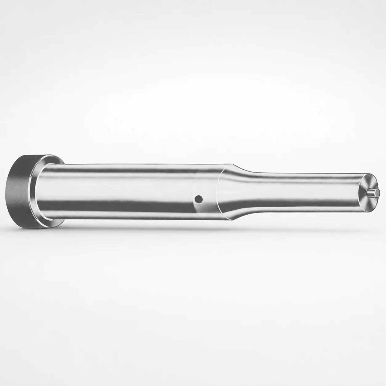
Inch XNP Coated Ejector Punches
Ejector Punches Inch (XNP coating) are designed for stable punching performance in production tooling. The coated surface helps resist wear and supports consistent ejection under repeated cycles.
- Inch ejector punch geometry for controlled punch guidance
- XNP coating to improve abrasion resistance in service
- Ground, coded length point design supports dimensional stability during assembly
- Suitable for progressive and transfer die punching operations
Specifications
750 configurations available
| Tip shape | D (Shank dia.) (in) | Jektole group | Standard [S] Point Length B & L (Length) (coded inch) | Alternate [B] Point Length B & L (Length) (coded inch) | Alternate [C] Point Length B & L (Length) (coded inch) | Alternate [D] Point Length B & L (Length) (coded inch) | Alternate [E] Point Length B & L (Length) (coded inch) | P Dimension (in) | W Dimension (in) | R Dimension (in) |
|---|---|---|---|---|---|---|---|---|---|---|
| H | 18(0.1875") | J2 | - | 150 ~ 400 | - | - | - | 0.062 ~ 0.1875 | 0.062 ~ 0.1875 | - |
| H | 18(0.1875") | J2 | 150 ~ 400 | - | - | - | - | 0.062 ~ 0.1875 | 0.062 ~ 0.1875 | - |
| H | 25(0.2500") | J3 | - | 150 ~ 400 | - | - | - | 0.08 ~ 0.25 | 0.08 ~ 0.0929 | - |
| H | 25(0.2500") | J3 | - | 150 ~ 400 | - | - | - | 0.08 ~ 0.25 | 0.093 ~ 0.25 | - |
| H | 25(0.2500") | J3 | 150 ~ 400 | - | - | - | - | 0.08 ~ 0.25 | 0.08 ~ 0.0929 | - |
| H | 25(0.2500") | J3 | 150 ~ 400 | - | - | - | - | 0.08 ~ 0.25 | 0.093 ~ 0.25 | - |
| H | 31(0.3125") | J4 | - | 150 ~ 600 | - | - | - | 0.115 ~ 0.3125 | 0.115 ~ 0.1249 | - |
| H | 31(0.3125") | J4 | - | 150 ~ 600 | - | - | - | 0.115 ~ 0.3125 | 0.125 ~ 0.3125 | - |
| H | 31(0.3125") | J4 | - | - | 175 ~ 600 | - | - | 0.115 ~ 0.3125 | 0.115 ~ 0.1249 | - |
| H | 31(0.3125") | J4 | - | - | 175 ~ 600 | - | - | 0.115 ~ 0.3125 | 0.125 ~ 0.3125 | - |
| H | 31(0.3125") | J4 | 150 ~ 600 | - | - | - | - | 0.115 ~ 0.3125 | 0.115 ~ 0.1249 | - |
| H | 31(0.3125") | J4 | 150 ~ 600 | - | - | - | - | 0.115 ~ 0.3125 | 0.125 ~ 0.3125 | - |
| H | 37(0.3750") | J6 | - | 175 ~ 625 | - | - | - | 0.158 ~ 0.375 | 0.158 ~ 0.1869 | - |
| H | 37(0.3750") | J6 | - | 175 ~ 625 | - | - | - | 0.158 ~ 0.375 | 0.187 ~ 0.375 | - |
| H | 37(0.3750") | J6 | - | - | 175 ~ 625 | - | - | 0.158 ~ 0.375 | 0.158 ~ 0.1869 | - |
| H | 37(0.3750") | J6 | - | - | 175 ~ 625 | - | - | 0.158 ~ 0.375 | 0.187 ~ 0.375 | - |
| H | 37(0.3750") | J6 | 175 ~ 625 | - | - | - | - | 0.158 ~ 0.375 | 0.158 ~ 0.1869 | - |
| H | 37(0.3750") | J6 | 175 ~ 625 | - | - | - | - | 0.158 ~ 0.375 | 0.187 ~ 0.375 | - |
| H | 43(0.4375") | J6 | - | - | 200 ~ 625 | - | - | 0.158 ~ 0.4375 | 0.158 ~ 0.1869 | - |
| H | 43(0.4375") | J6 | - | - | 200 ~ 625 | - | - | 0.158 ~ 0.4375 | 0.187 ~ 0.4375 | - |
| H | 43(0.4375") | J6 | 200 ~ 625 | - | - | - | - | 0.158 ~ 0.4375 | 0.158 ~ 0.1869 | - |
| H | 43(0.4375") | J6 | 200 ~ 625 | - | - | - | - | 0.158 ~ 0.4375 | 0.187 ~ 0.4375 | - |
| H | 50(0.5000") | J6 | - | - | 200 ~ 625 | - | - | 0.158 ~ 0.5 | 0.158 ~ 0.1869 | - |
| H | 50(0.5000") | J6 | - | - | 200 ~ 625 | - | - | 0.158 ~ 0.5 | 0.187 ~ 0.5 | - |
| H | 50(0.5000") | J6 | 200 ~ 625 | - | - | - | - | 0.158 ~ 0.5 | 0.158 ~ 0.1869 | - |
| H | 50(0.5000") | J6 | 200 ~ 625 | - | - | - | - | 0.158 ~ 0.5 | 0.187 ~ 0.5 | - |
| H | 62(0.6250") | J9 | - | - | - | 225 ~ 625 | - | 0.235 ~ 0.625 | 0.25 ~ 0.625 | - |
| H | 62(0.6250") | J9 | - | - | - | 225 ~ 625 | - | 0.235 ~ 0.625 | 0.235 ~ 0.2499 | - |
| H | 62(0.6250") | J9 | 225 ~ 625 | - | - | - | - | 0.235 ~ 0.625 | 0.25 ~ 0.625 | - |
| H | 62(0.6250") | J9 | 225 ~ 625 | - | - | - | - | 0.235 ~ 0.625 | 0.235 ~ 0.2499 | - |
| H | 75(0.7500") | J9 | - | - | - | 225 ~ 625 | - | 0.235 ~ 0.75 | 0.235 ~ 0.3119 | - |
| H | 75(0.7500") | J9 | - | - | - | 225 ~ 625 | - | 0.235 ~ 0.75 | 0.312 ~ 0.75 | - |
| H | 75(0.7500") | J9 | 225 ~ 625 | - | - | - | - | 0.235 ~ 0.75 | 0.235 ~ 0.3119 | - |
| H | 75(0.7500") | J9 | 225 ~ 625 | - | - | - | - | 0.235 ~ 0.75 | 0.312 ~ 0.75 | - |
| H | 87(0.8750") | J9 | - | - | - | 225 ~ 650 | - | 0.235 ~ 0.875 | 0.235 ~ 0.3119 | - |
| H | 87(0.8750") | J9 | - | - | - | 225 ~ 650 | - | 0.235 ~ 0.875 | 0.312 ~ 0.875 | - |
| H | 87(0.8750") | J9 | - | - | - | - | 225 ~ 650 | 0.235 ~ 0.875 | 0.235 ~ 0.3119 | - |
| H | 87(0.8750") | J9 | - | - | - | - | 225 ~ 650 | 0.235 ~ 0.875 | 0.312 ~ 0.875 | - |
| H | 87(0.8750") | J9 | 225 ~ 650 | - | - | - | - | 0.235 ~ 0.875 | 0.235 ~ 0.3119 | - |
| H | 87(0.8750") | J9 | 225 ~ 650 | - | - | - | - | 0.235 ~ 0.875 | 0.312 ~ 0.875 | - |
| H | 100(1.0000") | J9 | - | - | - | - | 250 ~ 650 | 0.235 ~ 1 | 0.235 ~ 0.3119 | - |
| H | 100(1.0000") | J9 | - | - | - | - | 250 ~ 650 | 0.235 ~ 1 | 0.312 ~ 1 | - |
| H | 100(1.0000") | J9 | 250 ~ 650 | - | - | - | - | 0.235 ~ 1 | 0.235 ~ 0.3119 | - |
| H | 100(1.0000") | J9 | 250 ~ 650 | - | - | - | - | 0.235 ~ 1 | 0.312 ~ 1 | - |
| H | 125(1.2500") | J12 | - | - | - | - | 250 ~ 700 | 0.281 ~ 1.25 | 0.281 ~ 0.3119 | - |
| H | 125(1.2500") | J12 | - | - | - | - | 250 ~ 700 | 0.281 ~ 1.25 | 0.312 ~ 1.25 | - |
| H | 125(1.2500") | J12 | 250 ~ 700 | - | - | - | - | 0.281 ~ 1.25 | 0.281 ~ 0.3119 | - |
| H | 125(1.2500") | J12 | 250 ~ 700 | - | - | - | - | 0.281 ~ 1.25 | 0.312 ~ 1.25 | - |
| H | 150(1.5000") | J12 | - | - | - | - | 250 ~ 700 | 0.281 ~ 1.5 | 0.281 ~ 0.3119 | - |
| H | 150(1.5000") | J12 | - | - | - | - | 250 ~ 700 | 0.281 ~ 1.5 | 0.312 ~ 1.5 | - |
Product Guide
Application Scenarios+
Inch ejector punch components like this are used inside injection and transfer die tooling to deliver stable, repeatable punching action and controlled ejection after forming. The XNP coated cutting and wear areas are well suited for production runs where abrasion at the punch tip must be minimized.
- Automotive and appliance stamped parts: progressive/transfer die sets benefit from the guided punch geometry and consistent point design, helping maintain hole/pierce quality across long cycles.
- Electronic connector and bracket punching: when thin-wall features require dimensional stability, the ground, coded length point supports reliable assembly fit while the coating helps protect the working surface.
- High-cycle manufacturing lines: the abrasion-resistant coating reduces wear progression on the tip and shank interface, supporting consistent ejection under repeated actuation.
Choose this variant when your tool design prioritizes tool-life extension in punching operations and repeatability of ejection behavior under continuous production load.
Material & Process Details+
This product is specified as XNP coated ejector punches. While the input data does not state the underlying steel grade, the process intent of XNP coating is to improve wear resistance at the working tip by forming a durable surface layer over the base metal.
- Coating benefit: reduced abrasion at the punch point supports more stable punching performance over repeated cycles.
- Heat treatment state: not specified in the provided parameters; final hardness and toughness balance should be confirmed against the supplier’s material certificate for the selected tip shape and shank diameter.
- Trade-offs: coated systems generally shift performance from bulk toughness to surface durability; ensure your base material selection still meets shock/load requirements of the die operation.
If you need hardness (HRC) confirmation, please provide the exact steel grade option used for your selection so we can map it to your expected wear/toughness targets.
Sizing & Selection Guide+
To select the correct ejector punch dimensions, match the shank diameter (D) and point length B & L to the required guide clearance and overall punch reach in your die set. From the specification, D is available in the range 18 ~ 250 in, and point length B & L is coded with standard values of 150 ~ 250 (coded inch).
- Tip shape selection: choose the required working profile from H, J, K, L, N, O, R, V, X, Y, Z based on your piercing geometry.
- Length matching: for longer reach, use alternate coded point length sets, such as 150–400, 150–600, 175–625, 200–625, 225–625, 225–650, and up to 250–700 depending on the chosen option group.
- Fit considerations: respect punch-guide clearance and seating features; the 0.05 ~ 1.625 P and 0.062 ~ 0.5 W dimensions indicate profile controls that can affect guidance and stress concentration.
- Tolerance: tolerance values are not provided; verify critical fits with your die drawing requirements for assembled interchangeability.
Finally, confirm that the selected Jektole group (e.g., J2, J3, J4, J6, J9, J12) aligns with your system’s standard geometry for consistent assembly.
Frequently Asked Questions
Which tip shape options (H/J/K/L/etc.) are available for these Inch XNP ejector punches, and how do I choose one for my punching profile?+
Tip shapes are available in H, J, K, L, N, O, R, V, X, Y, Z. Choose the profile that matches your required piercing edge geometry and part feature shape in the die design.
The correct tip shape also affects how the punch point engages the material, so confirm compatibility with your die clearance and piercing diameter targets.
What are the shank diameter and coded point length ranges for selecting the correct punch length?+
The shank diameter D is specified as 18 ~ 250 in. Standard point length B & L is coded for 150 ~ 250, with alternate coded ranges including 150–400, 150–600, 175–625, 200–625, 225–625, 225–650, 250–650, and up to 250–700.
Use these ranges to match the required reach and ensure the assembled punch engages consistently across the stroke.
Does the XNP coating directly improve tool life in punching applications, and what wear mechanisms should I expect it to address?+
The XNP coating is specified to protect cutting surfaces and improve abrasion resistance during service. In punching operations, this primarily helps slow wear progression at the punch point where sliding/friction and abrasive contact are highest.
For tool-life planning, still confirm base material toughness for your press load and shock conditions, since coating mainly targets surface durability.
How do the Jektole group selections (J2/J3/J4/J6/J9/J12) affect compatibility with my existing die tooling?+
The punch options specify a Jektole group selection: J2, J3, J4, J6, J9, J12. In practice, this is used to align geometry with an expected standard configuration for assembly and guidance.
To prevent misalignment, match your punch’s group to the die standard your tooling was designed around.
Are there critical profile dimensions (P, W, R) I must match when ordering an Inch XNP ejector punch?+
Yes. The specification lists profile/control dimensions: P = 0.05 ~ 1.625 in, W = 0.062 ~ 0.5 in, and R = 0.007 ~ 0.007 (constant range shown). These dimensions can affect guidance, seating behavior, and contact stress at the interface.
Use them to verify interchangeability against your die’s designed clearance and locating features.
Related Products






Need Custom Specifications?
Our engineering team can help with custom configurations, material selection, and volume pricing.