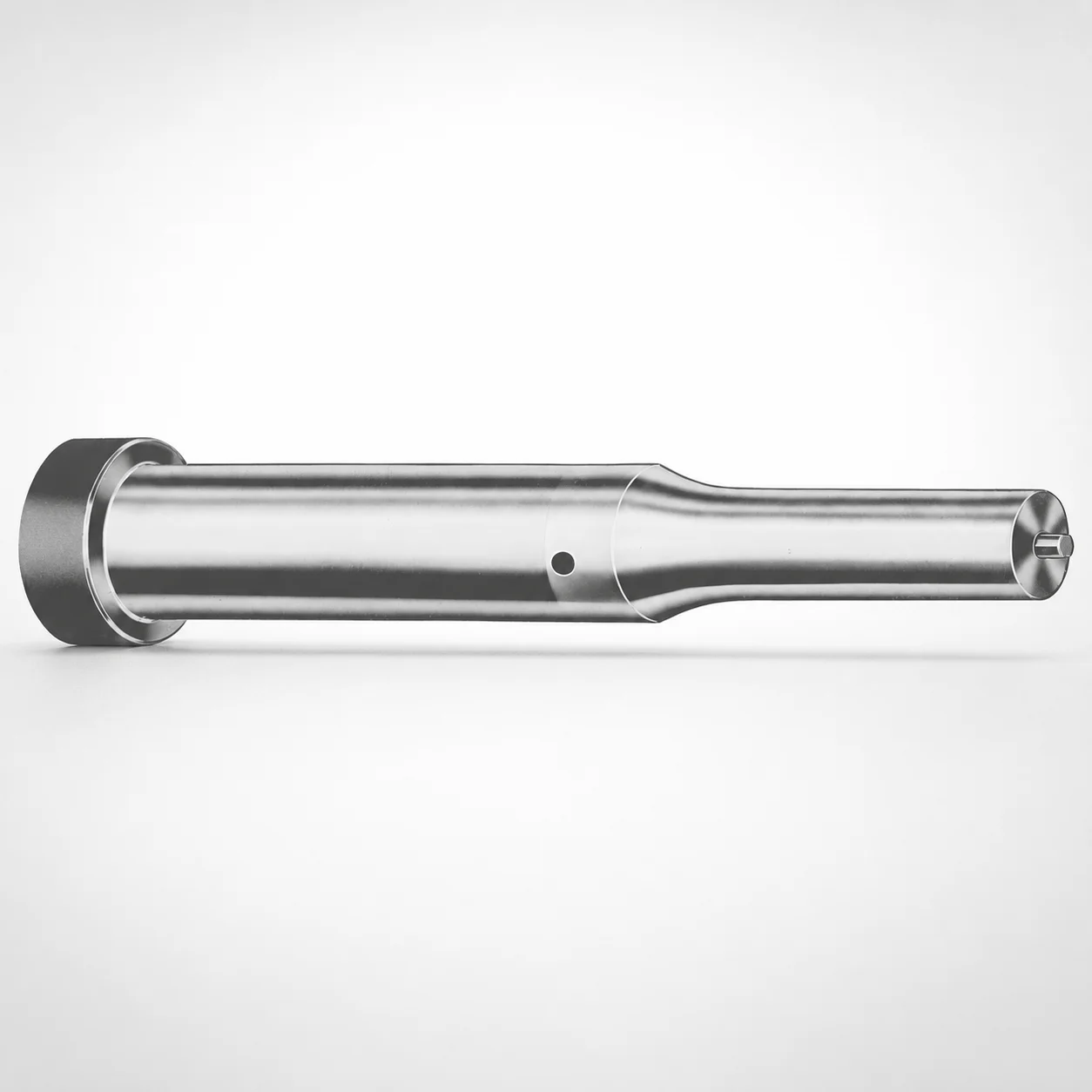
Inch Ejector Punches with XNM Coating
Inch ejector punches with XNM coating (Dayton) are designed to support stable ejection and controlled wear in punch tooling applications. The XNM coating package helps improve surface durability for repeated production cycles.
- Inch-format ejector punch design for consistent installation in tooling systems
- XNM coating improves resistance to wear during press operations
- Selectable tip geometry options for varied die contact and ejection requirements
- Supports die steel processing and alignment in progressive or transfer setups
Specifications
530 configurations available
| Tip shape | D (Shank dia.) (in) | Jektole group | Standard [S] Point Length B & L (Length) (coded inch) | Alternate [B] Point Length B & L (Length) (coded inch) | Alternate [C] Point Length B & L (Length) (coded inch) | Alternate [D] Point Length B & L (Length) (coded inch) | Alternate [E] Point Length B & L (Length) (coded inch) | P Dimension (in) | W Dimension (in) | R Dimension (in) |
|---|---|---|---|---|---|---|---|---|---|---|
| H | 18(0.1875") | J2 | - | 150 ~ 400 | - | - | - | 0.062 ~ 0.1875 | 0.062 ~ 0.1875 | - |
| H | 18(0.1875") | J2 | 150 ~ 400 | - | - | - | - | 0.062 ~ 0.1875 | 0.062 ~ 0.1875 | - |
| H | 25(0.2500") | J3 | - | 150 ~ 400 | - | - | - | 0.08 ~ 0.25 | 0.08 ~ 0.0929 | - |
| H | 25(0.2500") | J3 | - | 150 ~ 400 | - | - | - | 0.08 ~ 0.25 | 0.093 ~ 0.25 | - |
| H | 25(0.2500") | J3 | 150 ~ 400 | - | - | - | - | 0.08 ~ 0.25 | 0.08 ~ 0.0929 | - |
| H | 25(0.2500") | J3 | 150 ~ 400 | - | - | - | - | 0.08 ~ 0.25 | 0.093 ~ 0.25 | - |
| H | 31(0.3125") | J4 | - | 150 ~ 600 | - | - | - | 0.115 ~ 0.3125 | 0.115 ~ 0.1249 | - |
| H | 31(0.3125") | J4 | - | 150 ~ 600 | - | - | - | 0.115 ~ 0.3125 | 0.125 ~ 0.3125 | - |
| H | 31(0.3125") | J4 | - | - | 175 ~ 600 | - | - | 0.115 ~ 0.3125 | 0.115 ~ 0.1249 | - |
| H | 31(0.3125") | J4 | - | - | 175 ~ 600 | - | - | 0.115 ~ 0.3125 | 0.125 ~ 0.3125 | - |
| H | 31(0.3125") | J4 | 150 ~ 600 | - | - | - | - | 0.115 ~ 0.3125 | 0.115 ~ 0.1249 | - |
| H | 31(0.3125") | J4 | 150 ~ 600 | - | - | - | - | 0.115 ~ 0.3125 | 0.125 ~ 0.3125 | - |
| H | 37(0.3750") | J6 | - | 175 ~ 625 | - | - | - | 0.158 ~ 0.375 | 0.158 ~ 0.1869 | - |
| H | 37(0.3750") | J6 | - | 175 ~ 625 | - | - | - | 0.158 ~ 0.375 | 0.187 ~ 0.375 | - |
| H | 37(0.3750") | J6 | - | - | 175 ~ 625 | - | - | 0.158 ~ 0.375 | 0.158 ~ 0.1869 | - |
| H | 37(0.3750") | J6 | - | - | 175 ~ 625 | - | - | 0.158 ~ 0.375 | 0.187 ~ 0.375 | - |
| H | 37(0.3750") | J6 | 175 ~ 625 | - | - | - | - | 0.158 ~ 0.375 | 0.158 ~ 0.1869 | - |
| H | 37(0.3750") | J6 | 175 ~ 625 | - | - | - | - | 0.158 ~ 0.375 | 0.187 ~ 0.375 | - |
| H | 43(0.4375") | J6 | - | - | 200 ~ 625 | - | - | 0.158 ~ 0.4375 | 0.158 ~ 0.1869 | - |
| H | 43(0.4375") | J6 | - | - | 200 ~ 625 | - | - | 0.158 ~ 0.4375 | 0.187 ~ 0.4375 | - |
| H | 43(0.4375") | J6 | 200 ~ 625 | - | - | - | - | 0.158 ~ 0.4375 | 0.158 ~ 0.1869 | - |
| H | 43(0.4375") | J6 | 200 ~ 625 | - | - | - | - | 0.158 ~ 0.4375 | 0.187 ~ 0.4375 | - |
| H | 50(0.5000") | J6 | - | - | 200 ~ 625 | - | - | 0.158 ~ 0.5 | 0.158 ~ 0.1869 | - |
| H | 50(0.5000") | J6 | - | - | 200 ~ 625 | - | - | 0.158 ~ 0.5 | 0.187 ~ 0.5 | - |
| H | 50(0.5000") | J6 | 200 ~ 625 | - | - | - | - | 0.158 ~ 0.5 | 0.158 ~ 0.1869 | - |
| H | 50(0.5000") | J6 | 200 ~ 625 | - | - | - | - | 0.158 ~ 0.5 | 0.187 ~ 0.5 | - |
| H | 62(0.6250") | J9 | - | - | - | 225 ~ 625 | - | 0.235 ~ 0.625 | 0.25 ~ 0.625 | - |
| H | 62(0.6250") | J9 | - | - | - | 225 ~ 625 | - | 0.235 ~ 0.625 | 0.235 ~ 0.2499 | - |
| H | 62(0.6250") | J9 | 225 ~ 625 | - | - | - | - | 0.235 ~ 0.625 | 0.25 ~ 0.625 | - |
| H | 62(0.6250") | J9 | 225 ~ 625 | - | - | - | - | 0.235 ~ 0.625 | 0.235 ~ 0.2499 | - |
| H | 75(0.7500") | J9 | - | - | - | 225 ~ 625 | - | 0.235 ~ 0.75 | 0.235 ~ 0.3119 | - |
| H | 75(0.7500") | J9 | - | - | - | 225 ~ 625 | - | 0.235 ~ 0.75 | 0.312 ~ 0.75 | - |
| H | 75(0.7500") | J9 | 225 ~ 625 | - | - | - | - | 0.235 ~ 0.75 | 0.235 ~ 0.3119 | - |
| H | 75(0.7500") | J9 | 225 ~ 625 | - | - | - | - | 0.235 ~ 0.75 | 0.312 ~ 0.75 | - |
| H | 87(0.8750") | J9 | - | - | - | 225 ~ 650 | - | 0.235 ~ 0.875 | 0.235 ~ 0.3119 | - |
| H | 87(0.8750") | J9 | - | - | - | 225 ~ 650 | - | 0.235 ~ 0.875 | 0.312 ~ 0.875 | - |
| H | 87(0.8750") | J9 | - | - | - | - | 225 ~ 650 | 0.235 ~ 0.875 | 0.235 ~ 0.3119 | - |
| H | 87(0.8750") | J9 | - | - | - | - | 225 ~ 650 | 0.235 ~ 0.875 | 0.312 ~ 0.875 | - |
| H | 87(0.8750") | J9 | 225 ~ 650 | - | - | - | - | 0.235 ~ 0.875 | 0.235 ~ 0.3119 | - |
| H | 87(0.8750") | J9 | 225 ~ 650 | - | - | - | - | 0.235 ~ 0.875 | 0.312 ~ 0.875 | - |
| H | 100(1.0000") | J9 | - | - | - | - | 250 ~ 650 | 0.235 ~ 1 | 0.235 ~ 0.3119 | - |
| H | 100(1.0000") | J9 | - | - | - | - | 250 ~ 650 | 0.235 ~ 1 | 0.312 ~ 1 | - |
| H | 100(1.0000") | J9 | 250 ~ 650 | - | - | - | - | 0.235 ~ 1 | 0.235 ~ 0.3119 | - |
| H | 100(1.0000") | J9 | 250 ~ 650 | - | - | - | - | 0.235 ~ 1 | 0.312 ~ 1 | - |
| H | 125(1.2500") | J12 | - | - | - | - | 250 ~ 700 | 0.281 ~ 1.25 | 0.281 ~ 0.3119 | - |
| H | 125(1.2500") | J12 | - | - | - | - | 250 ~ 700 | 0.281 ~ 1.25 | 0.312 ~ 1.25 | - |
| H | 125(1.2500") | J12 | 250 ~ 700 | - | - | - | - | 0.281 ~ 1.25 | 0.281 ~ 0.3119 | - |
| H | 125(1.2500") | J12 | 250 ~ 700 | - | - | - | - | 0.281 ~ 1.25 | 0.312 ~ 1.25 | - |
| J | 18(0.1875") | J2 | - | 150 ~ 400 | - | - | - | 0.062 ~ 0.1875 | 0.062 ~ 0.1875 | - |
| J | 18(0.1875") | J2 | 150 ~ 400 | - | - | - | - | 0.062 ~ 0.1875 | 0.062 ~ 0.1875 | - |
Product Guide
Application Scenarios+
In progressive and transfer press tooling, this type of inch ejector punch is used to drive parts out of die cavities while maintaining repeatable alignment through cycles. The variant with XNM coating is particularly suited for higher-wear environments where punch-to-die contact and sliding abrasion can degrade performance over time.
- Automotive and appliance press dies: Use ejector punches to stabilize ejection of stamped components. The coating helps reduce surface wear during long production runs where frequent cycling is expected.
- Consumer/industrial component housings: For housings or brackets requiring controlled part release, select the appropriate tip shape (H, J, K, L, N, O, R, V, X, Y, Z) to match die contact points and prevent gouging.
- Precision alignment in multi-station tooling: The inch shank diameter range supports consistent installation within standard punch tooling systems, helping maintain uniform ejection height across stations.
By matching tip geometry and length codes to the die design, engineers can balance ejection force paths with durability needs.
Material & Process Details+
The provided specifications focus on inch-format geometry and XNM coating, but no steel grade, heat-treatment state, or base hardness (HRC) is explicitly listed. As a result, material property claims such as specific wear/toughness trade-offs, substrate hardness, or whether the punch is quenched & tempered, nitrided, or pre-hardened cannot be stated from the available data.
- XNM coating role: Designed to improve surface durability and wear resistance during punch-to-die rubbing and repeated press operations.
- Tip geometry impact: Selecting tip shapes (H, J, K, L, N, O, R, V, X, Y, Z) affects contact area and load distribution, which influences how quickly surfaces experience abrasion.
If you share the substrate material/heat treatment and target hardness, the page can be updated to include grade equivalency (e.g., SKD61/H13, SKH51/M2) and accurate HRC-based guidance.
Sizing & Selection Guide+
Selection starts with matching the punch shank diameter to the guide and tooling bore system. For this series, the D (shank dia.) range is 18 ~ 125 in, so choose the diameter that fits your press die and retaining components with the required functional clearance.
- Tip shape: Pick from H, J, K, L, N, O, R, V, X, Y, Z to align the contact footprint with the part ejection interface and reduce localized stress.
- Length selection: Use the point length codes for Standard [S] B & L = 150 ~ 250 (coded inch). For Alternate [B], C, and D/E variants, lengths span up to 150~600, 175~625, 225~650, 250~700 depending on the code set.
- Critical dimensions: Match P (0.05 ~ 0.687 in) and W (0.062 ~ 0.312 in) to your die contact geometry; keep tolerances consistent with your assembly and ejection clearance.
When integrating across multiple stations, verify that the chosen length code achieves the required ejection stroke and that fits in the tooling system account for manufacturing tolerances.
Frequently Asked Questions
Which tip shape options (H/J/K/…/Z) should I choose for stable part ejection in press dies?+
Select the tip shape based on the punch-to-die contact interface and the desired contact footprint. This series offers H, J, K, L, N, O, R, V, X, Y, Z, letting you tailor load distribution to reduce localized wear at the ejection point. For multi-station progressive or transfer tooling, confirm the selected geometry matches the part release path and contact zone.
How do I match the ejector punch length codes (S/B/C/D/E) to my die cavity/core layout?+
Use the coded B & L point length ranges for your required working length. The Standard [S] option covers 150 ~ 250 (coded inch), while Alternate [B] spans multiple options (e.g., 150~400, 150~600, 175~625). Choose the variant that provides the closest functional length while maintaining correct ejection stroke and clearance.
What shank diameter (D) range is available, and how does it affect compatibility with tooling guides?+
The available D (shank dia.) range is 18 ~ 125 in. Select the diameter that matches your press die’s punch-retainer and guide system for proper installation and alignment. Because fit depends on your tooling tolerances, confirm functional clearance so the punch moves reliably without binding during cycling.
How does the XNM coating influence wear performance for repeated press operations?+
The XNM coating is specified to improve surface durability and resistance to wear during punch tooling use. It is intended to help manage abrasion at the punch working surfaces where repeated press contact occurs. Pair coating selection with correct tip geometry to maintain stable ejection and reduce localized wear.
Which additional dimensions (P, W, R) are most important for die contact geometry?+
In addition to D and length codes, this series provides dimension ranges for P (0.05 ~ 0.687 in), W (0.062 ~ 0.312 in), and R (0.007 ~ 0.007 in). These govern aspects of the punch profile that directly affect how the tip contacts the die or part surface. Verify these dimensions align with your die contact design and the required clearance for reliable ejection.
Related Products






Need Custom Specifications?
Our engineering team can help with custom configurations, material selection, and volume pricing.