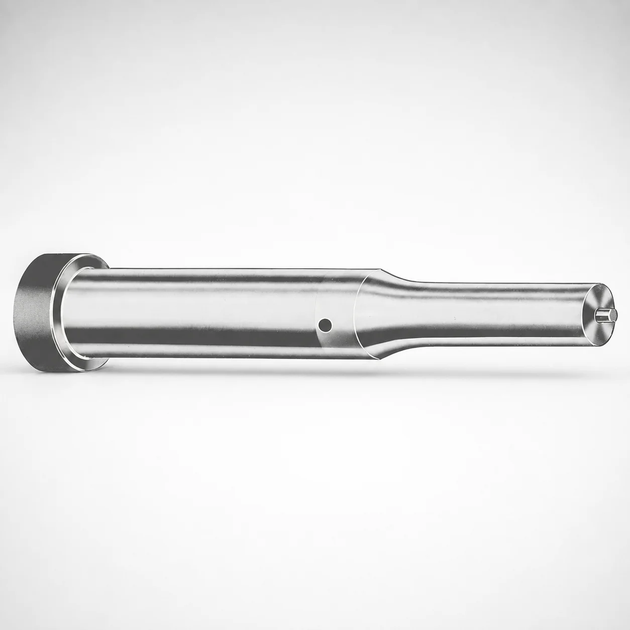
Inch Ejector Punches XNAP Coating
Inch ejector punches with XNAP coating (DAYTON) are designed for reliable part ejection and consistent punch performance in production tooling. Tip geometry options help match common close-clearance forming requirements.
- Close-fit ejector punch tip shapes for stable blanking and ejection
- XNAP coating supports wear resistance and smoother punch operation
- Engineered ground point and shank geometry improves assembly compatibility
- Suitable for inch-based die blocks in progressive and transfer dies
Specifications
750 configurations available
| Tip shape | D (Shank dia.) (in) | Standard [S] Point Length B & L (Length) (coded inch) | Alternate [B] Point Length B & L (Length) (coded inch) | Alternate [C] Point Length B & L (Length) (coded inch) | Alternate [D] Point Length B & L (Length) (coded inch) | Alternate [E] Point Length B & L (Length) (coded inch) | P Dimension (in) | W Dimension (in) | R Dimension (in) |
|---|---|---|---|---|---|---|---|---|---|
| H | 18(0.1875") | - | 150 ~ 400 | - | - | - | 0.062 ~ 0.1875 | 0.062 ~ 0.1875 | - |
| H | 18(0.1875") | 150 ~ 400 | - | - | - | - | 0.062 ~ 0.1875 | 0.062 ~ 0.1875 | - |
| H | 25(0.2500") | - | 150 ~ 400 | - | - | - | 0.08 ~ 0.25 | 0.08 ~ 0.0929 | - |
| H | 25(0.2500") | - | 150 ~ 400 | - | - | - | 0.08 ~ 0.25 | 0.093 ~ 0.25 | - |
| H | 25(0.2500") | 150 ~ 400 | - | - | - | - | 0.08 ~ 0.25 | 0.08 ~ 0.0929 | - |
| H | 25(0.2500") | 150 ~ 400 | - | - | - | - | 0.08 ~ 0.25 | 0.093 ~ 0.25 | - |
| H | 31(0.3125") | - | 150 ~ 600 | - | - | - | 0.115 ~ 0.3125 | 0.115 ~ 0.1249 | - |
| H | 31(0.3125") | - | 150 ~ 600 | - | - | - | 0.115 ~ 0.3125 | 0.125 ~ 0.3125 | - |
| H | 31(0.3125") | - | - | 175 ~ 600 | - | - | 0.115 ~ 0.3125 | 0.115 ~ 0.1249 | - |
| H | 31(0.3125") | - | - | 175 ~ 600 | - | - | 0.115 ~ 0.3125 | 0.125 ~ 0.3125 | - |
| H | 31(0.3125") | 150 ~ 600 | - | - | - | - | 0.115 ~ 0.3125 | 0.115 ~ 0.1249 | - |
| H | 31(0.3125") | 150 ~ 600 | - | - | - | - | 0.115 ~ 0.3125 | 0.125 ~ 0.3125 | - |
| H | 37(0.3750") | - | 175 ~ 625 | - | - | - | 0.158 ~ 0.375 | 0.158 ~ 0.1869 | - |
| H | 37(0.3750") | - | 175 ~ 625 | - | - | - | 0.158 ~ 0.375 | 0.187 ~ 0.375 | - |
| H | 37(0.3750") | - | - | 175 ~ 625 | - | - | 0.158 ~ 0.375 | 0.158 ~ 0.1869 | - |
| H | 37(0.3750") | - | - | 175 ~ 625 | - | - | 0.158 ~ 0.375 | 0.187 ~ 0.375 | - |
| H | 37(0.3750") | 175 ~ 625 | - | - | - | - | 0.158 ~ 0.375 | 0.158 ~ 0.1869 | - |
| H | 37(0.3750") | 175 ~ 625 | - | - | - | - | 0.158 ~ 0.375 | 0.187 ~ 0.375 | - |
| H | 43(0.4375") | - | - | 200 ~ 625 | - | - | 0.158 ~ 0.4375 | 0.158 ~ 0.1869 | - |
| H | 43(0.4375") | - | - | 200 ~ 625 | - | - | 0.158 ~ 0.4375 | 0.187 ~ 0.4375 | - |
| H | 43(0.4375") | 200 ~ 625 | - | - | - | - | 0.158 ~ 0.4375 | 0.158 ~ 0.1869 | - |
| H | 43(0.4375") | 200 ~ 625 | - | - | - | - | 0.158 ~ 0.4375 | 0.187 ~ 0.4375 | - |
| H | 50(0.5000") | - | - | 200 ~ 625 | - | - | 0.158 ~ 0.5 | 0.158 ~ 0.1869 | - |
| H | 50(0.5000") | - | - | 200 ~ 625 | - | - | 0.158 ~ 0.5 | 0.187 ~ 0.5 | - |
| H | 50(0.5000") | 200 ~ 625 | - | - | - | - | 0.158 ~ 0.5 | 0.158 ~ 0.1869 | - |
| H | 50(0.5000") | 200 ~ 625 | - | - | - | - | 0.158 ~ 0.5 | 0.187 ~ 0.5 | - |
| H | 62(0.6250") | - | - | - | 225 ~ 625 | - | 0.235 ~ 0.625 | 0.25 ~ 0.625 | - |
| H | 62(0.6250") | - | - | - | 225 ~ 625 | - | 0.235 ~ 0.625 | 0.235 ~ 0.2499 | - |
| H | 62(0.6250") | 225 ~ 625 | - | - | - | - | 0.235 ~ 0.625 | 0.25 ~ 0.625 | - |
| H | 62(0.6250") | 225 ~ 625 | - | - | - | - | 0.235 ~ 0.625 | 0.235 ~ 0.2499 | - |
| H | 75(0.7500") | - | - | - | 225 ~ 625 | - | 0.235 ~ 0.75 | 0.235 ~ 0.3119 | - |
| H | 75(0.7500") | - | - | - | 225 ~ 625 | - | 0.235 ~ 0.75 | 0.312 ~ 0.75 | - |
| H | 75(0.7500") | 225 ~ 625 | - | - | - | - | 0.235 ~ 0.75 | 0.235 ~ 0.3119 | - |
| H | 75(0.7500") | 225 ~ 625 | - | - | - | - | 0.235 ~ 0.75 | 0.312 ~ 0.75 | - |
| H | 87(0.8750") | - | - | - | 225 ~ 650 | - | 0.235 ~ 0.875 | 0.235 ~ 0.3119 | - |
| H | 87(0.8750") | - | - | - | 225 ~ 650 | - | 0.235 ~ 0.875 | 0.312 ~ 0.875 | - |
| H | 87(0.8750") | - | - | - | - | 225 ~ 650 | 0.235 ~ 0.875 | 0.235 ~ 0.3119 | - |
| H | 87(0.8750") | - | - | - | - | 225 ~ 650 | 0.235 ~ 0.875 | 0.312 ~ 0.875 | - |
| H | 87(0.8750") | 225 ~ 650 | - | - | - | - | 0.235 ~ 0.875 | 0.235 ~ 0.3119 | - |
| H | 87(0.8750") | 225 ~ 650 | - | - | - | - | 0.235 ~ 0.875 | 0.312 ~ 0.875 | - |
| H | 100(1.0000") | - | - | - | - | 250 ~ 650 | 0.235 ~ 1 | 0.235 ~ 0.3119 | - |
| H | 100(1.0000") | - | - | - | - | 250 ~ 650 | 0.235 ~ 1 | 0.312 ~ 1 | - |
| H | 100(1.0000") | 250 ~ 650 | - | - | - | - | 0.235 ~ 1 | 0.235 ~ 0.3119 | - |
| H | 100(1.0000") | 250 ~ 650 | - | - | - | - | 0.235 ~ 1 | 0.312 ~ 1 | - |
| H | 125(1.2500") | - | - | - | - | 250 ~ 700 | 0.281 ~ 1.25 | 0.281 ~ 0.3119 | - |
| H | 125(1.2500") | - | - | - | - | 250 ~ 700 | 0.281 ~ 1.25 | 0.312 ~ 1.25 | - |
| H | 125(1.2500") | 250 ~ 700 | - | - | - | - | 0.281 ~ 1.25 | 0.281 ~ 0.3119 | - |
| H | 125(1.2500") | 250 ~ 700 | - | - | - | - | 0.281 ~ 1.25 | 0.312 ~ 1.25 | - |
| H | 150(1.5000") | - | - | - | - | 250 ~ 700 | 0.281 ~ 1.5 | 0.281 ~ 0.3119 | - |
| H | 150(1.5000") | - | - | - | - | 250 ~ 700 | 0.281 ~ 1.5 | 0.312 ~ 1.5 | - |
Product Guide
Application Scenarios+
In injection and forming tooling, inch ejector punches are used to drive molded or formed parts out of the cavity/core set after each cycle. The XNAP-coated variant is well-suited to applications where consistent ejection force and long die life are critical, such as automotive connector housings and electrical terminal component molds that operate at high throughput.
- Progressive/transfer die blanking and ejection: The close-fit tip shapes (H, J, K, L, N, O, R, V, X, Y, Z) help maintain stable guidance and smoother ejection during repeated forming steps.
- Thin-wall or tight-clearance work: Optimized tip geometry supports reliable part separation where side loading can otherwise accelerate punch wear.
- Production tooling with abrasive contact: The XNAP coating is selected to improve wear resistance and maintain punch operating consistency over extended runs.
Shank geometry and ground point design improve compatibility during assembly into inch-based die blocks and standard ejector stations.
Material & Process Details+
The provided specification set describes the inch ejector punch variant and its XNAP coating, but it does not list the underlying steel grade or heat-treatment state. For material selection and performance planning, treat the key differentiator here as the coating system that enhances surface durability under sliding and abrasive ejection conditions.
- XNAP coating: chosen to increase wear resistance and reduce galling risk, helping maintain stable punch operation during high-cycle production.
- Hardness and trade-offs: exact HRC values are not provided in the input data; in practice, coating performance depends on an appropriate base hardness to balance wear resistance with toughness against chipping at the tip.
- Manufacturing process (inferred from geometry needs): tip geometries are ground and the point/shank are manufactured to tight dimensional requirements for reliable assembly fit in inch tooling.
If you need a hardness/heat-treat confirmation (HRC) for qualification or warranty documentation, share the steel grade and heat-treatment data your project requires.
Sizing & Selection Guide+
To select the correct inch ejector punch dimensions, match three areas to your mold/die geometry: shank diameter (D), point/tip length (B and L coded length), and tip geometry.
- Shank diameter D (in): choose from 18 ~ 250 to fit your inch-based ejector bushing or bore. Ensure the bore/punch fit prevents excessive clearance (can cause wobble) while avoiding interference that can increase ejection friction.
- Point length / overall length options: standard coded inch lengths are 150 ~ 250. Alternate ranges are available, including 150–400, 150–600, 175–625, 200–625, 225–625, 225–650, and up to 250–700 depending on the selected alternate category.
- Tip shape: select one of H, J, K, L, N, O, R, V, X, Y, Z to suit close-clearance forming and guidance requirements.
Dimensions marked by P (0.05 ~ 1.625) and W (0.062 ~ 0.5) define the fine geometry; validate these against your cavity/core knock-out space and the desired contact pattern. Tolerance/fit values are not provided in the input data—confirm with your supplier drawing for final GD&T.
Frequently Asked Questions
Which tip geometries (H/J/K/L/N/O/R/V/X/Y/Z) should I choose for close-clearance blanking and stable ejection?+
This series supports multiple tip shape options: H, J, K, L, N, O, R, V, X, Y, Z. For close-fit requirements, select the tip geometry designed for stable guidance and reduced side loading during blanking/ejection. If you share your die clearance and expected ejector stroke direction, we can help map the best-fit tip style to your configuration.
What shank diameter (D) range is available for inch ejector punches in this series, and how does it affect fit?+
The available D (shank diameter) range is 18 ~ 250 (in). Your ejector bore/bushing diameter must be selected for reliable fit—too much clearance can cause punch misalignment and uneven wear, while too tight a fit can increase ejection friction. Use the punch D value to match your inch-based ejector guide specifications.
How do the coded point length ranges (B & L) map to the required ejector travel and packaging space?+
The standard point length B & L is coded in the range 150 ~ 250. Alternate ranges are also available, including 150–400, 150–600, 175–625, 200–625, 225–625, 225–650, 250–650, and up to 250–700 depending on the selected alternate category. Choose the range that provides sufficient effective length for ejection while respecting your available die stack-up space.
What are the roles of the P, W, and R dimensions in punch geometry selection?+
This series provides geometry parameters P (0.05 ~ 1.625) and W (0.062 ~ 0.5), as well as R = 0.007 in the provided specification set. These values correspond to the fine tip and edge geometry that influence contact pattern and stability during ejection. Validate these against your cavity/core knock-out clearance to avoid interference and to maintain predictable part separation.
Does the XNAP coating change compatibility requirements versus non-coated punches?+
The input data specifies an XNAP coating intended to improve wear resistance and support smoother punch operation. Coating can reduce abrasive wear and help maintain performance over longer production runs, but dimensional and fit compatibility is still governed by D, length ranges, and tip geometry. Confirm clearances and final GD&T with the project drawings to ensure reliable assembly fit.
Related Products






Need Custom Specifications?
Our engineering team can help with custom configurations, material selection, and volume pricing.