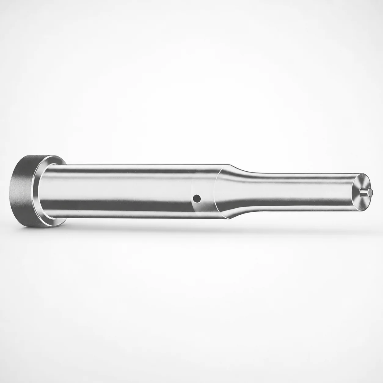
Ejector Punches - Inch, XNAD Coating
Ejector Punches - Inch, XNAD Coating (Dayton) deliver a controlled punch form factor for reliable ejection in tooling. The XNAD coated surface supports consistent performance across repeated production cycles.
- Inch ejector punch geometry designed for stable ejection in dies
- XNAD coating to improve wear resistance and reduce abrasive damage
- Engineered tip options for matching tool layouts and material needs
- Typical use in stamping and die-set assemblies requiring punch accuracy
Specifications
750 configurations available
| Tip shape | D (Shank dia.) (in) | Jektole group | Standard [S] Point Length B & L (Length) (coded inch) | Alternate [B] Point Length B & L (Length) (coded inch) | Alternate [C] Point Length B & L (Length) (coded inch) | Alternate [D] Point Length B & L (Length) (coded inch) | Alternate [E] Point Length B & L (Length) (coded inch) | P Dimension (in) | W Dimension (in) | R Dimension (in) |
|---|---|---|---|---|---|---|---|---|---|---|
| H | 18(0.1875") | J2 | - | 150 ~ 400 | - | - | - | 0.062 ~ 0.1875 | 0.062 ~ 0.1875 | - |
| H | 18(0.1875") | J2 | 150 ~ 400 | - | - | - | - | 0.062 ~ 0.1875 | 0.062 ~ 0.1875 | - |
| H | 25(0.2500") | J3 | - | 150 ~ 400 | - | - | - | 0.08 ~ 0.25 | 0.08 ~ 0.0929 | - |
| H | 25(0.2500") | J3 | - | 150 ~ 400 | - | - | - | 0.08 ~ 0.25 | 0.093 ~ 0.25 | - |
| H | 25(0.2500") | J3 | 150 ~ 400 | - | - | - | - | 0.08 ~ 0.25 | 0.08 ~ 0.0929 | - |
| H | 25(0.2500") | J3 | 150 ~ 400 | - | - | - | - | 0.08 ~ 0.25 | 0.093 ~ 0.25 | - |
| H | 31(0.3125") | J4 | - | 150 ~ 600 | - | - | - | 0.115 ~ 0.3125 | 0.115 ~ 0.1249 | - |
| H | 31(0.3125") | J4 | - | 150 ~ 600 | - | - | - | 0.115 ~ 0.3125 | 0.125 ~ 0.3125 | - |
| H | 31(0.3125") | J4 | - | - | 175 ~ 600 | - | - | 0.115 ~ 0.3125 | 0.115 ~ 0.1249 | - |
| H | 31(0.3125") | J4 | - | - | 175 ~ 600 | - | - | 0.115 ~ 0.3125 | 0.125 ~ 0.3125 | - |
| H | 31(0.3125") | J4 | 150 ~ 600 | - | - | - | - | 0.115 ~ 0.3125 | 0.115 ~ 0.1249 | - |
| H | 31(0.3125") | J4 | 150 ~ 600 | - | - | - | - | 0.115 ~ 0.3125 | 0.125 ~ 0.3125 | - |
| H | 37(0.3750") | J6 | - | 175 ~ 625 | - | - | - | 0.158 ~ 0.375 | 0.158 ~ 0.1869 | - |
| H | 37(0.3750") | J6 | - | 175 ~ 625 | - | - | - | 0.158 ~ 0.375 | 0.187 ~ 0.375 | - |
| H | 37(0.3750") | J6 | - | - | 175 ~ 625 | - | - | 0.158 ~ 0.375 | 0.158 ~ 0.1869 | - |
| H | 37(0.3750") | J6 | - | - | 175 ~ 625 | - | - | 0.158 ~ 0.375 | 0.187 ~ 0.375 | - |
| H | 37(0.3750") | J6 | 175 ~ 625 | - | - | - | - | 0.158 ~ 0.375 | 0.158 ~ 0.1869 | - |
| H | 37(0.3750") | J6 | 175 ~ 625 | - | - | - | - | 0.158 ~ 0.375 | 0.187 ~ 0.375 | - |
| H | 43(0.4375") | J6 | - | - | 200 ~ 625 | - | - | 0.158 ~ 0.4375 | 0.158 ~ 0.1869 | - |
| H | 43(0.4375") | J6 | - | - | 200 ~ 625 | - | - | 0.158 ~ 0.4375 | 0.187 ~ 0.4375 | - |
| H | 43(0.4375") | J6 | 200 ~ 625 | - | - | - | - | 0.158 ~ 0.4375 | 0.158 ~ 0.1869 | - |
| H | 43(0.4375") | J6 | 200 ~ 625 | - | - | - | - | 0.158 ~ 0.4375 | 0.187 ~ 0.4375 | - |
| H | 50(0.5000") | J6 | - | - | 200 ~ 625 | - | - | 0.158 ~ 0.5 | 0.158 ~ 0.1869 | - |
| H | 50(0.5000") | J6 | - | - | 200 ~ 625 | - | - | 0.158 ~ 0.5 | 0.187 ~ 0.5 | - |
| H | 50(0.5000") | J6 | 200 ~ 625 | - | - | - | - | 0.158 ~ 0.5 | 0.158 ~ 0.1869 | - |
| H | 50(0.5000") | J6 | 200 ~ 625 | - | - | - | - | 0.158 ~ 0.5 | 0.187 ~ 0.5 | - |
| H | 62(0.6250") | J9 | - | - | - | 225 ~ 625 | - | 0.235 ~ 0.625 | 0.25 ~ 0.625 | - |
| H | 62(0.6250") | J9 | - | - | - | 225 ~ 625 | - | 0.235 ~ 0.625 | 0.235 ~ 0.2499 | - |
| H | 62(0.6250") | J9 | 225 ~ 625 | - | - | - | - | 0.235 ~ 0.625 | 0.25 ~ 0.625 | - |
| H | 62(0.6250") | J9 | 225 ~ 625 | - | - | - | - | 0.235 ~ 0.625 | 0.235 ~ 0.2499 | - |
| H | 75(0.7500") | J9 | - | - | - | 225 ~ 625 | - | 0.235 ~ 0.75 | 0.235 ~ 0.3119 | - |
| H | 75(0.7500") | J9 | - | - | - | 225 ~ 625 | - | 0.235 ~ 0.75 | 0.312 ~ 0.75 | - |
| H | 75(0.7500") | J9 | 225 ~ 625 | - | - | - | - | 0.235 ~ 0.75 | 0.235 ~ 0.3119 | - |
| H | 75(0.7500") | J9 | 225 ~ 625 | - | - | - | - | 0.235 ~ 0.75 | 0.312 ~ 0.75 | - |
| H | 87(0.8750") | J9 | - | - | - | 225 ~ 650 | - | 0.235 ~ 0.875 | 0.235 ~ 0.3119 | - |
| H | 87(0.8750") | J9 | - | - | - | 225 ~ 650 | - | 0.235 ~ 0.875 | 0.312 ~ 0.875 | - |
| H | 87(0.8750") | J9 | - | - | - | - | 225 ~ 650 | 0.235 ~ 0.875 | 0.235 ~ 0.3119 | - |
| H | 87(0.8750") | J9 | - | - | - | - | 225 ~ 650 | 0.235 ~ 0.875 | 0.312 ~ 0.875 | - |
| H | 87(0.8750") | J9 | 225 ~ 650 | - | - | - | - | 0.235 ~ 0.875 | 0.235 ~ 0.3119 | - |
| H | 87(0.8750") | J9 | 225 ~ 650 | - | - | - | - | 0.235 ~ 0.875 | 0.312 ~ 0.875 | - |
| H | 100(1.0000") | J9 | - | - | - | - | 250 ~ 650 | 0.235 ~ 1 | 0.235 ~ 0.3119 | - |
| H | 100(1.0000") | J9 | - | - | - | - | 250 ~ 650 | 0.235 ~ 1 | 0.312 ~ 1 | - |
| H | 100(1.0000") | J9 | 250 ~ 650 | - | - | - | - | 0.235 ~ 1 | 0.235 ~ 0.3119 | - |
| H | 100(1.0000") | J9 | 250 ~ 650 | - | - | - | - | 0.235 ~ 1 | 0.312 ~ 1 | - |
| H | 125(1.2500") | J12 | - | - | - | - | 250 ~ 700 | 0.281 ~ 1.25 | 0.281 ~ 0.3119 | - |
| H | 125(1.2500") | J12 | - | - | - | - | 250 ~ 700 | 0.281 ~ 1.25 | 0.312 ~ 1.25 | - |
| H | 125(1.2500") | J12 | 250 ~ 700 | - | - | - | - | 0.281 ~ 1.25 | 0.281 ~ 0.3119 | - |
| H | 125(1.2500") | J12 | 250 ~ 700 | - | - | - | - | 0.281 ~ 1.25 | 0.312 ~ 1.25 | - |
| H | 150(1.5000") | J12 | - | - | - | - | 250 ~ 700 | 0.281 ~ 1.5 | 0.281 ~ 0.3119 | - |
| H | 150(1.5000") | J12 | - | - | - | - | 250 ~ 700 | 0.281 ~ 1.5 | 0.312 ~ 1.5 | - |
Product Guide
Application Scenarios+
Ejector punches with an XNAD coated surface are commonly specified for stable part release in precision die sets, where repeat ejection cycles can otherwise accelerate wear at the punch tip.
- Automotive and appliance stamping dies: Use these inch-standard ejector punches to drive clean strip ejection with controlled geometry. The hard-wearing coating helps resist abrasive contact against workpiece surfaces and die inserts.
- Die casting tool ejection systems: Inward die-set ejectors benefit from consistent punch form factors and long-running wear reduction, supporting uniform ejection under high cycle rates.
- Thin-gauge or textured components: Select the appropriate tip shape (H/J/K/L/N/O/R/V/X/Y/Z) and coded point length ranges to match clearances and avoid scuffing while maintaining reliable release.
Choose the variant with your required shank diameter and point length range to align with cavity/core shut-off distances and ejector stroke requirements.
Material & Process Details+
The provided specification set for this series focuses on inch dimensions and XNAD coating; no explicit base steel grade or hardness (HRC) is listed in the input data. As a result, hardness and metallurgical heat-treatment states (e.g., through-hardened, quenched & tempered, nitrided) cannot be stated without the missing material datasheet.
From an application standpoint, the XNAD coating is selected to improve wear resistance and reduce abrasive damage at the punch tip during repeated ejection.
- Coating advantage: Lower tip wear supports punch life and helps maintain ejection consistency across production cycles.
- Design trade-off: Coating performance depends on contact pressure, surface finish, and the selected tip shape; choose geometry to manage edge loading.
If you share the punch steel grade or drawing note, we can map it to an equivalent grade and include the correct HRC/heat-treatment details.
Sizing & Selection Guide+
Select dimensions by matching the ejector punch shank and point lengths to the die-set layout while respecting the available coded ranges.
- Shank diameter (D): Choose D in the range 18 ~ 250 in to fit your ejector bore/guide system and maintain proper alignment. Verify the corresponding bore size and clearance for stable guidance.
- Tip/point length (S and alternates): Standard coded point length uses 150 ~ 250 (coded inch). If needed, alternate ranges are available such as 150 ~ 400 / 150 ~ 600 / 175 ~ 625 / 200 ~ 625, and longer options including 225 ~ 625, 225 ~ 650, 250 ~ 650, 250 ~ 700, depending on the selected alternate code (B/C/D/E).
- Cross-section dimensions: Use P (0.05 ~ 1.625) and W (0.062 ~ 0.5) to match your tool geometry constraints near the punch interface.
Confirm tolerance/fit requirements from your die design drawings: the shank diameter must align with guide bores, while the selected point length must provide sufficient ejection travel without bottoming.
Frequently Asked Questions
Which XNAD-coated ejector punch tip shapes are available for this inch standard series?+
This series offers multiple tip shape options: H, J, K, L, N, O, R, V, X, Y, Z. Choose the tip shape based on contact conditions and how the punch interfaces with the part or strip during ejection. Pair the tip shape with your required point length coding to maintain the correct working projection.
How do I choose the correct coded point length for S vs B/C/D/E alternate options?+
The input specifies a standard [S] point length range of 150 ~ 250 (coded inch). Alternate point length ranges vary by code: for example, B offers 150 ~ 400, 150 ~ 600, or 175 ~ 625, while C includes options such as 175 ~ 600 and 200 ~ 625.
Select the code that provides the working projection needed for your cavity/core ejection clearance, ensuring the punch does not bottom out in the die stack.
What shank diameter range (D) is available for selecting an ejector punch for my guide system?+
The available D (shank diameter) range is 18 ~ 250 in for this series. Use this to confirm compatibility with your ejector bore and guiding components. Then verify that the selected point length (S or alternates) matches your required ejection stroke and part release distance.
What are the allowable dimension ranges for P, W, and R when matching tool interface geometry?+
The specification lists P as 0.05 ~ 1.625 and W as 0.062 ~ 0.5 (in). The R dimension is given as 0.007 ~ 0.007 (in), indicating a fixed value based on the provided range format.
Match these dimensions to any nearby die features (e.g., recesses, reliefs, or clearance surfaces) to avoid interference during ejection.
Does the provided data include base steel grade, hardness (HRC), or heat treatment for this punch?+
The input data specifies the XNAD coating and dimensional parameters, but it does not provide the base steel grade, hardness (HRC), or heat-treatment state. Therefore, we cannot reliably state whether the punch is quenched & tempered, nitrided, or pre-hardened based on the supplied information.
If you can provide the steel grade or a drawing note, we can add the exact heat treatment and hardness behavior.
Related Products






Need Custom Specifications?
Our engineering team can help with custom configurations, material selection, and volume pricing.