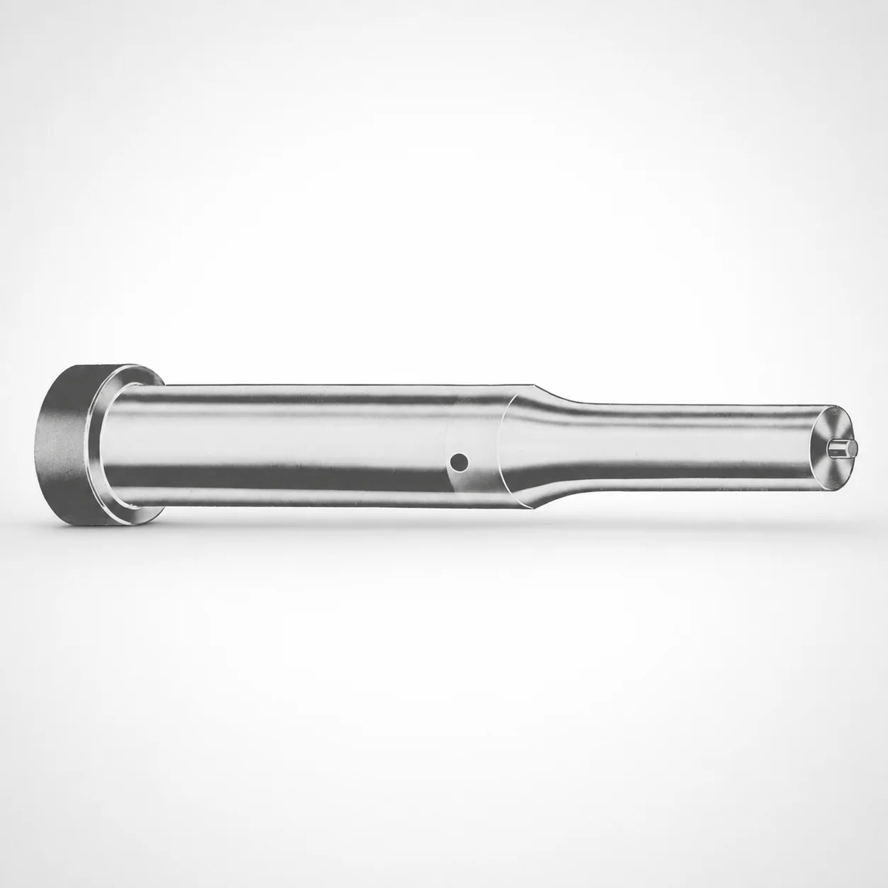
Inch Ejector Punches XNA Coating
Inch ejector punches XNA coating are designed for consistent part ejection in tooling with standardized punch geometry. The XNA coated surface helps reduce friction and improve wear resistance for reliable production cycles.
- Inch punch format with standardized part-number standardization to streamline procurement workflows
- XNA coating for improved wear and smoother sliding in the die set
- Controlled tip and shank fit across multiple tip shapes and index groups for compatibility
- Suitable for press tooling applications requiring repeatable ejection performance
Specifications
750 configurations available
| Tip shape | D (Shank dia.) (in) | Jektole group | Standard [S] Point Length B & L (Length) (coded inch) | Alternate [B] Point Length B & L (Length) (coded inch) | Alternate [C] Point Length B & L (Length) (coded inch) | Alternate [D] Point Length B & L (Length) (coded inch) | Alternate [E] Point Length B & L (Length) (coded inch) | P Dimension (in) | W Dimension (in) | R Dimension (in) |
|---|---|---|---|---|---|---|---|---|---|---|
| H | 18(0.1875") | J2 | - | 150 ~ 400 | - | - | - | 0.062 ~ 0.1875 | 0.062 ~ 0.1875 | - |
| H | 18(0.1875") | J2 | 150 ~ 400 | - | - | - | - | 0.062 ~ 0.1875 | 0.062 ~ 0.1875 | - |
| H | 25(0.2500") | J3 | - | 150 ~ 400 | - | - | - | 0.08 ~ 0.25 | 0.08 ~ 0.0929 | - |
| H | 25(0.2500") | J3 | - | 150 ~ 400 | - | - | - | 0.08 ~ 0.25 | 0.093 ~ 0.25 | - |
| H | 25(0.2500") | J3 | 150 ~ 400 | - | - | - | - | 0.08 ~ 0.25 | 0.08 ~ 0.0929 | - |
| H | 25(0.2500") | J3 | 150 ~ 400 | - | - | - | - | 0.08 ~ 0.25 | 0.093 ~ 0.25 | - |
| H | 31(0.3125") | J4 | - | 150 ~ 600 | - | - | - | 0.115 ~ 0.3125 | 0.115 ~ 0.1249 | - |
| H | 31(0.3125") | J4 | - | 150 ~ 600 | - | - | - | 0.115 ~ 0.3125 | 0.125 ~ 0.3125 | - |
| H | 31(0.3125") | J4 | - | - | 175 ~ 600 | - | - | 0.115 ~ 0.3125 | 0.115 ~ 0.1249 | - |
| H | 31(0.3125") | J4 | - | - | 175 ~ 600 | - | - | 0.115 ~ 0.3125 | 0.125 ~ 0.3125 | - |
| H | 31(0.3125") | J4 | 150 ~ 600 | - | - | - | - | 0.115 ~ 0.3125 | 0.115 ~ 0.1249 | - |
| H | 31(0.3125") | J4 | 150 ~ 600 | - | - | - | - | 0.115 ~ 0.3125 | 0.125 ~ 0.3125 | - |
| H | 37(0.3750") | J6 | - | 175 ~ 625 | - | - | - | 0.158 ~ 0.375 | 0.158 ~ 0.1869 | - |
| H | 37(0.3750") | J6 | - | 175 ~ 625 | - | - | - | 0.158 ~ 0.375 | 0.187 ~ 0.375 | - |
| H | 37(0.3750") | J6 | - | - | 175 ~ 625 | - | - | 0.158 ~ 0.375 | 0.158 ~ 0.1869 | - |
| H | 37(0.3750") | J6 | - | - | 175 ~ 625 | - | - | 0.158 ~ 0.375 | 0.187 ~ 0.375 | - |
| H | 37(0.3750") | J6 | 175 ~ 625 | - | - | - | - | 0.158 ~ 0.375 | 0.158 ~ 0.1869 | - |
| H | 37(0.3750") | J6 | 175 ~ 625 | - | - | - | - | 0.158 ~ 0.375 | 0.187 ~ 0.375 | - |
| H | 43(0.4375") | J6 | - | - | 200 ~ 625 | - | - | 0.158 ~ 0.4375 | 0.158 ~ 0.1869 | - |
| H | 43(0.4375") | J6 | - | - | 200 ~ 625 | - | - | 0.158 ~ 0.4375 | 0.187 ~ 0.4375 | - |
| H | 43(0.4375") | J6 | 200 ~ 625 | - | - | - | - | 0.158 ~ 0.4375 | 0.158 ~ 0.1869 | - |
| H | 43(0.4375") | J6 | 200 ~ 625 | - | - | - | - | 0.158 ~ 0.4375 | 0.187 ~ 0.4375 | - |
| H | 50(0.5000") | J6 | - | - | 200 ~ 625 | - | - | 0.158 ~ 0.5 | 0.158 ~ 0.1869 | - |
| H | 50(0.5000") | J6 | - | - | 200 ~ 625 | - | - | 0.158 ~ 0.5 | 0.187 ~ 0.5 | - |
| H | 50(0.5000") | J6 | 200 ~ 625 | - | - | - | - | 0.158 ~ 0.5 | 0.158 ~ 0.1869 | - |
| H | 50(0.5000") | J6 | 200 ~ 625 | - | - | - | - | 0.158 ~ 0.5 | 0.187 ~ 0.5 | - |
| H | 62(0.6250") | J9 | - | - | - | 225 ~ 625 | - | 0.235 ~ 0.625 | 0.25 ~ 0.625 | - |
| H | 62(0.6250") | J9 | - | - | - | 225 ~ 625 | - | 0.235 ~ 0.625 | 0.235 ~ 0.2499 | - |
| H | 62(0.6250") | J9 | 225 ~ 625 | - | - | - | - | 0.235 ~ 0.625 | 0.25 ~ 0.625 | - |
| H | 62(0.6250") | J9 | 225 ~ 625 | - | - | - | - | 0.235 ~ 0.625 | 0.235 ~ 0.2499 | - |
| H | 75(0.7500") | J9 | - | - | - | 225 ~ 625 | - | 0.235 ~ 0.75 | 0.235 ~ 0.3119 | - |
| H | 75(0.7500") | J9 | - | - | - | 225 ~ 625 | - | 0.235 ~ 0.75 | 0.312 ~ 0.75 | - |
| H | 75(0.7500") | J9 | 225 ~ 625 | - | - | - | - | 0.235 ~ 0.75 | 0.235 ~ 0.3119 | - |
| H | 75(0.7500") | J9 | 225 ~ 625 | - | - | - | - | 0.235 ~ 0.75 | 0.312 ~ 0.75 | - |
| H | 87(0.8750") | J9 | - | - | - | 225 ~ 650 | - | 0.235 ~ 0.875 | 0.235 ~ 0.3119 | - |
| H | 87(0.8750") | J9 | - | - | - | 225 ~ 650 | - | 0.235 ~ 0.875 | 0.312 ~ 0.875 | - |
| H | 87(0.8750") | J9 | - | - | - | - | 225 ~ 650 | 0.235 ~ 0.875 | 0.235 ~ 0.3119 | - |
| H | 87(0.8750") | J9 | - | - | - | - | 225 ~ 650 | 0.235 ~ 0.875 | 0.312 ~ 0.875 | - |
| H | 87(0.8750") | J9 | 225 ~ 650 | - | - | - | - | 0.235 ~ 0.875 | 0.235 ~ 0.3119 | - |
| H | 87(0.8750") | J9 | 225 ~ 650 | - | - | - | - | 0.235 ~ 0.875 | 0.312 ~ 0.875 | - |
| H | 100(1.0000") | J9 | - | - | - | - | 250 ~ 650 | 0.235 ~ 1 | 0.235 ~ 0.3119 | - |
| H | 100(1.0000") | J9 | - | - | - | - | 250 ~ 650 | 0.235 ~ 1 | 0.312 ~ 1 | - |
| H | 100(1.0000") | J9 | 250 ~ 650 | - | - | - | - | 0.235 ~ 1 | 0.235 ~ 0.3119 | - |
| H | 100(1.0000") | J9 | 250 ~ 650 | - | - | - | - | 0.235 ~ 1 | 0.312 ~ 1 | - |
| H | 125(1.2500") | J12 | - | - | - | - | 250 ~ 700 | 0.281 ~ 1.25 | 0.281 ~ 0.3119 | - |
| H | 125(1.2500") | J12 | - | - | - | - | 250 ~ 700 | 0.281 ~ 1.25 | 0.312 ~ 1.25 | - |
| H | 125(1.2500") | J12 | 250 ~ 700 | - | - | - | - | 0.281 ~ 1.25 | 0.281 ~ 0.3119 | - |
| H | 125(1.2500") | J12 | 250 ~ 700 | - | - | - | - | 0.281 ~ 1.25 | 0.312 ~ 1.25 | - |
| H | 150(1.5000") | J12 | - | - | - | - | 250 ~ 700 | 0.281 ~ 1.5 | 0.281 ~ 0.3119 | - |
| H | 150(1.5000") | J12 | - | - | - | - | 250 ~ 700 | 0.281 ~ 1.5 | 0.312 ~ 1.5 | - |
Product Guide
Application Scenarios+
Inch ejector punches with an XNA coated tip are used in standard press and die tooling where reliable ejection repeatability is critical. Their controlled shank-to-tip geometry and compatibility across multiple tip shapes help maintain consistent contact during the ejection stroke, reducing variability from cycle to cycle.
- Automotive and appliance press tooling: Use for ejection of stamped or formed components where sliding resistance must be controlled to avoid galling and maintain stable ejection force across high production runs.
- Die sets for household/electrical parts: Suitable when multiple tip shapes (H, J, K, L, N, O, R, V, X, Y, Z) are required for different cavity details, while a coated surface supports smoother movement in the die pocket.
- General manufacturing transfer/press stations: The indexed Jektole groups (J2, J3, J4, J6, J9, J12) simplify matching to established designs, supporting predictable ejection performance with long service intervals.
XNA coating is specifically suited for these applications because it helps reduce friction and wear at the punch tip where die-contact forces concentrate.
Material & Process Details+
The provided product data specifies an XNA coating for wear reduction on an inch ejector punch, but it does not list the base steel grade or heat-treatment condition. For selection, the key technical focus is how the coating interacts with die-contact motion to improve sliding stability and reduce tip wear during repeated ejection.
- XNA-coated wear surface: Designed to reduce friction and improve wear resistance, supporting longer service life in ejection zones.
- Wear vs. toughness trade-off: In ejector systems, high wear resistance at the tip is typically prioritized; however, mechanical toughness of the underlying steel still governs resistance to chipping under impact loads (steel grade not specified here).
- Heat treatment: Specific states such as quenched & tempered or nitrided are not provided in the supplied information, so they should be confirmed with the supplier documentation for hardness and core toughness targets.
When comparing variants, select based on required tip wear life and the die set motion conditions, ensuring the steel condition supports the coating’s intended performance.
Sizing & Selection Guide+
To select the correct ejector punch, match both the shank diameter (D) and the point length to your die pocket/core dimensions. This series supports D = 18 ~ 250 in and point length codes with base range S = 150 ~ 250 (coded inch).
- Choose tip shape first: Select one of the available tip shapes (H, J, K, L, N, O, R, V, X, Y, Z) based on how the ejector interfaces with the part geometry and cavity details.
- Select the correct index/Jektole group: Ensure your design alignment matches one of J2, J3, J4, J6, J9, J12 to maintain compatibility with established tool layouts.
- Match point length (B & L coded): Depending on the alternate coding, use the offered ranges such as 150–400, 150–600, 175–625, 200–625, 225–625, 225–650, 250–700, etc.
- Account for small critical dimensions: The series lists P = 0.05 ~ 1.625 in, W = 0.062 ~ 0.5 in, and R = 0.007 in. These should align with your ejector contact profile to avoid interference or under-support.
Where possible, verify fit by checking your punch guide bore and clearance strategy against the selected D and profile dimensions.
Frequently Asked Questions
Which tip shapes are available for the inch ejector punches XNA-coated series 250300511435, and how should I choose among them?+
What shank diameter (D) range is covered, and how do I match it to my die set guide bore?+
How do I select the correct point length for cavity/core spacing using the S and alternate B/L coded inch ranges?+
What is the role of the Jektole group (J2–J12) in ensuring compatibility within an existing mold design?+
Does the XNA coating affect selection for high-cycle ejection, and what base steel/heat treatment should I verify?+
Related Products






Need Custom Specifications?
Our engineering team can help with custom configurations, material selection, and volume pricing.