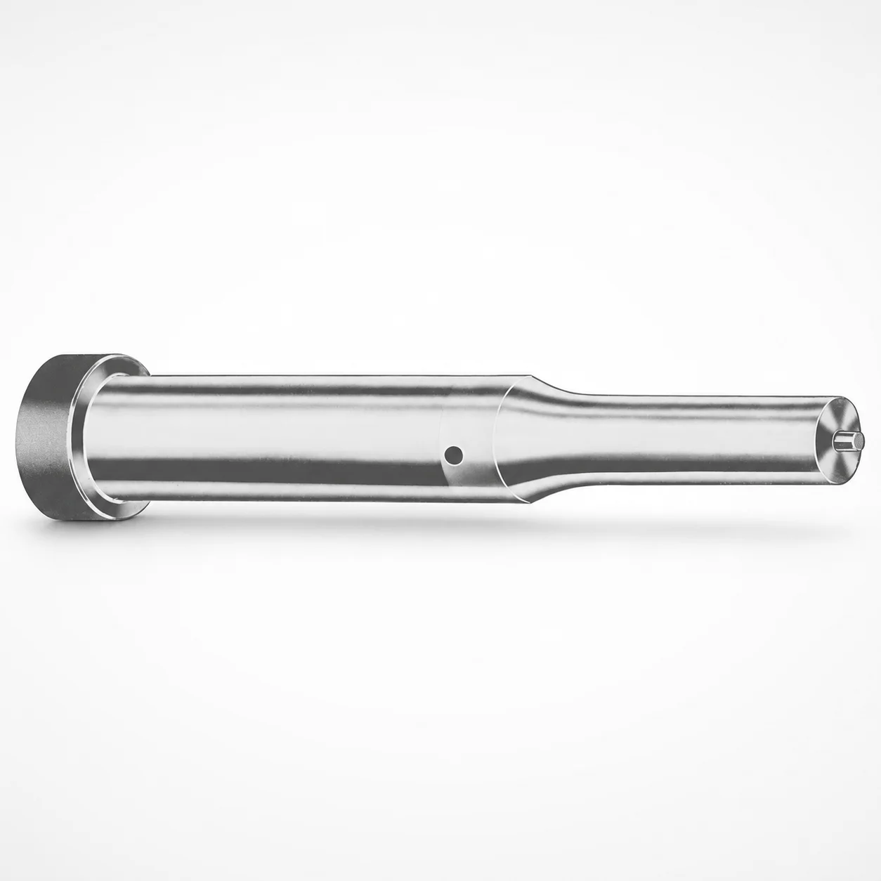
Inch Ejector Punches XCDP Coating
Inch ejector punches XCDP coating deliver controlled wear resistance for punch-and-die applications. The DAYTON LAMINA part standard helps streamline part identification, simplifying procurement and documentation across projects.
- XCDP coated punch surfaces support consistent ejection in production cycles
- Inch punch format designed for compatibility with standard tooling layouts
- Available tip shapes and coded point lengths help match specific molding needs
- Built to the DAYTON LAMINA part number format for easier ordering workflows
Specifications
750 configurations available
| Tip shape | D (Shank dia.) (in) | Jektole group | Standard [S] Point Length B & L (Length) (coded inch) | Alternate [B] Point Length B & L (Length) (coded inch) | Alternate [C] Point Length B & L (Length) (coded inch) | Alternate [D] Point Length B & L (Length) (coded inch) | Alternate [E] Point Length B & L (Length) (coded inch) | P Dimension (in) | W Dimension (in) | R Dimension (in) |
|---|---|---|---|---|---|---|---|---|---|---|
| H | 18(0.1875") | J2 | - | 150 ~ 400 | - | - | - | 0.062 ~ 0.1875 | 0.062 ~ 0.1875 | - |
| H | 18(0.1875") | J2 | 150 ~ 400 | - | - | - | - | 0.062 ~ 0.1875 | 0.062 ~ 0.1875 | - |
| H | 25(0.2500") | J3 | - | 150 ~ 400 | - | - | - | 0.08 ~ 0.25 | 0.08 ~ 0.0929 | - |
| H | 25(0.2500") | J3 | - | 150 ~ 400 | - | - | - | 0.08 ~ 0.25 | 0.093 ~ 0.25 | - |
| H | 25(0.2500") | J3 | 150 ~ 400 | - | - | - | - | 0.08 ~ 0.25 | 0.08 ~ 0.0929 | - |
| H | 25(0.2500") | J3 | 150 ~ 400 | - | - | - | - | 0.08 ~ 0.25 | 0.093 ~ 0.25 | - |
| H | 31(0.3125") | J4 | - | 150 ~ 600 | - | - | - | 0.115 ~ 0.3125 | 0.115 ~ 0.1249 | - |
| H | 31(0.3125") | J4 | - | 150 ~ 600 | - | - | - | 0.115 ~ 0.3125 | 0.125 ~ 0.3125 | - |
| H | 31(0.3125") | J4 | - | - | 175 ~ 600 | - | - | 0.115 ~ 0.3125 | 0.115 ~ 0.1249 | - |
| H | 31(0.3125") | J4 | - | - | 175 ~ 600 | - | - | 0.115 ~ 0.3125 | 0.125 ~ 0.3125 | - |
| H | 31(0.3125") | J4 | 150 ~ 600 | - | - | - | - | 0.115 ~ 0.3125 | 0.115 ~ 0.1249 | - |
| H | 31(0.3125") | J4 | 150 ~ 600 | - | - | - | - | 0.115 ~ 0.3125 | 0.125 ~ 0.3125 | - |
| H | 37(0.3750") | J6 | - | 175 ~ 625 | - | - | - | 0.158 ~ 0.375 | 0.158 ~ 0.1869 | - |
| H | 37(0.3750") | J6 | - | 175 ~ 625 | - | - | - | 0.158 ~ 0.375 | 0.187 ~ 0.375 | - |
| H | 37(0.3750") | J6 | - | - | 175 ~ 625 | - | - | 0.158 ~ 0.375 | 0.158 ~ 0.1869 | - |
| H | 37(0.3750") | J6 | - | - | 175 ~ 625 | - | - | 0.158 ~ 0.375 | 0.187 ~ 0.375 | - |
| H | 37(0.3750") | J6 | 175 ~ 625 | - | - | - | - | 0.158 ~ 0.375 | 0.158 ~ 0.1869 | - |
| H | 37(0.3750") | J6 | 175 ~ 625 | - | - | - | - | 0.158 ~ 0.375 | 0.187 ~ 0.375 | - |
| H | 43(0.4375") | J6 | - | - | 200 ~ 625 | - | - | 0.158 ~ 0.4375 | 0.158 ~ 0.1869 | - |
| H | 43(0.4375") | J6 | - | - | 200 ~ 625 | - | - | 0.158 ~ 0.4375 | 0.187 ~ 0.4375 | - |
| H | 43(0.4375") | J6 | 200 ~ 625 | - | - | - | - | 0.158 ~ 0.4375 | 0.158 ~ 0.1869 | - |
| H | 43(0.4375") | J6 | 200 ~ 625 | - | - | - | - | 0.158 ~ 0.4375 | 0.187 ~ 0.4375 | - |
| H | 50(0.5000") | J6 | - | - | 200 ~ 625 | - | - | 0.158 ~ 0.5 | 0.158 ~ 0.1869 | - |
| H | 50(0.5000") | J6 | - | - | 200 ~ 625 | - | - | 0.158 ~ 0.5 | 0.187 ~ 0.5 | - |
| H | 50(0.5000") | J6 | 200 ~ 625 | - | - | - | - | 0.158 ~ 0.5 | 0.158 ~ 0.1869 | - |
| H | 50(0.5000") | J6 | 200 ~ 625 | - | - | - | - | 0.158 ~ 0.5 | 0.187 ~ 0.5 | - |
| H | 62(0.6250") | J9 | - | - | - | 225 ~ 625 | - | 0.235 ~ 0.625 | 0.25 ~ 0.625 | - |
| H | 62(0.6250") | J9 | - | - | - | 225 ~ 625 | - | 0.235 ~ 0.625 | 0.235 ~ 0.2499 | - |
| H | 62(0.6250") | J9 | 225 ~ 625 | - | - | - | - | 0.235 ~ 0.625 | 0.25 ~ 0.625 | - |
| H | 62(0.6250") | J9 | 225 ~ 625 | - | - | - | - | 0.235 ~ 0.625 | 0.235 ~ 0.2499 | - |
| H | 75(0.7500") | J9 | - | - | - | 225 ~ 625 | - | 0.235 ~ 0.75 | 0.235 ~ 0.3119 | - |
| H | 75(0.7500") | J9 | - | - | - | 225 ~ 625 | - | 0.235 ~ 0.75 | 0.312 ~ 0.75 | - |
| H | 75(0.7500") | J9 | 225 ~ 625 | - | - | - | - | 0.235 ~ 0.75 | 0.235 ~ 0.3119 | - |
| H | 75(0.7500") | J9 | 225 ~ 625 | - | - | - | - | 0.235 ~ 0.75 | 0.312 ~ 0.75 | - |
| H | 87(0.8750") | J9 | - | - | - | 225 ~ 650 | - | 0.235 ~ 0.875 | 0.235 ~ 0.3119 | - |
| H | 87(0.8750") | J9 | - | - | - | 225 ~ 650 | - | 0.235 ~ 0.875 | 0.312 ~ 0.875 | - |
| H | 87(0.8750") | J9 | - | - | - | - | 225 ~ 650 | 0.235 ~ 0.875 | 0.235 ~ 0.3119 | - |
| H | 87(0.8750") | J9 | - | - | - | - | 225 ~ 650 | 0.235 ~ 0.875 | 0.312 ~ 0.875 | - |
| H | 87(0.8750") | J9 | 225 ~ 650 | - | - | - | - | 0.235 ~ 0.875 | 0.235 ~ 0.3119 | - |
| H | 87(0.8750") | J9 | 225 ~ 650 | - | - | - | - | 0.235 ~ 0.875 | 0.312 ~ 0.875 | - |
| H | 100(1.0000") | J9 | - | - | - | - | 250 ~ 650 | 0.235 ~ 1 | 0.235 ~ 0.3119 | - |
| H | 100(1.0000") | J9 | - | - | - | - | 250 ~ 650 | 0.235 ~ 1 | 0.312 ~ 1 | - |
| H | 100(1.0000") | J9 | 250 ~ 650 | - | - | - | - | 0.235 ~ 1 | 0.235 ~ 0.3119 | - |
| H | 100(1.0000") | J9 | 250 ~ 650 | - | - | - | - | 0.235 ~ 1 | 0.312 ~ 1 | - |
| H | 125(1.2500") | J12 | - | - | - | - | 250 ~ 700 | 0.281 ~ 1.25 | 0.281 ~ 0.3119 | - |
| H | 125(1.2500") | J12 | - | - | - | - | 250 ~ 700 | 0.281 ~ 1.25 | 0.312 ~ 1.25 | - |
| H | 125(1.2500") | J12 | 250 ~ 700 | - | - | - | - | 0.281 ~ 1.25 | 0.281 ~ 0.3119 | - |
| H | 125(1.2500") | J12 | 250 ~ 700 | - | - | - | - | 0.281 ~ 1.25 | 0.312 ~ 1.25 | - |
| H | 150(1.5000") | J12 | - | - | - | - | 250 ~ 700 | 0.281 ~ 1.5 | 0.281 ~ 0.3119 | - |
| H | 150(1.5000") | J12 | - | - | - | - | 250 ~ 700 | 0.281 ~ 1.5 | 0.312 ~ 1.5 | - |
Product Guide
Application Scenarios+
In injection molding toolsets, inch ejector punches with an XCDP coated working surface are commonly used to maintain stable ejection force over long production runs. The coating is especially suited for applications where the punch tip repeatedly slides or rubs against plastic, sprue residue, or ejector return hardware, helping reduce wear-driven changes to ejection behavior.
- Automotive connector and housing molds: Use these punches in ejector layouts requiring consistent ejection through many cycle counts. The controlled wear performance helps preserve tip geometry during continuous operation.
- Consumer electronics and appliance parts: Apply them in molds with frequent format changes and long production batches where tooling repeatability matters. The inch format supports standard tooling layouts and practical cavity/core spacing.
- General-purpose industrial components: Match coded point lengths and tip shapes to specific molded-part undercuts and gate/runner placements, improving part ejection reliability.
DAYTON LAMINA part standard supports part identification and ordering across engineering and procurement workflows, reducing mix-ups when managing multi-cavity or multi-project tooling.
Material & Process Details+
These inch ejector punches are specified by coating selection (XCDP) to deliver durable wear performance at the punch working surface. While the provided data does not list a specific steel grade or hardness value, the engineering intent is clear: the XCDP surface treatment is selected to improve wear resistance and maintain consistent ejection contact conditions.
- Wear vs. toughness trade-off: Wear-focused surface treatments typically prioritize resistance to abrasion and sliding wear at the tip; designers must still consider that aggressive wear resistance can sometimes affect surface brittleness if the base steel and heat treatment are not properly matched.
- Heat treatment state: Not specified in the provided parameters; confirm the underlying core hardness and temper condition in the purchase documentation for critical molds.
If you need to compare alternative materials, selection should be based on your expected abrasion level, cycle count, and allowable dimensional drift—especially when different tip shapes (H through Z) are used with varying P/W dimensions.
Sizing & Selection Guide+
Select an ejector punch size by matching the shank diameter D and the coded point length B & L to your mold ejector system and cavity/core requirements. Available D ranges from 18 to 250 in, so choose the largest diameter that still fits your ejector guide bore and clearance constraints.
- Tip shape: Choose from H, J, K, L, N, O, R, V, X, Y, Z based on the molded-part geometry and desired ejection contact pattern.
- Point length (B & L): Standard S point length is 150 to 250 coded inch. Alternate lengths expand to ranges such as 150–400, 150–600, 175–625, 200–625, 225–650, 250–700 depending on the alternate coding group.
- Contact geometry dimensions: Use P = 0.05–1.625 in and W = 0.062–0.5 in to ensure the tip profile aligns with your ejector stroke and clearance to the cavity wall.
Verify fit and clearance in ejector bushings/guides, and treat the coded dimensions as part-specific values—your final stack-up should include tolerances on the surrounding ejector components, not just the punch dimensions.
Frequently Asked Questions
Which tip shapes (H–Z) are available for DAYTON inch ejector punches with XCDP coating?+
What shank diameter D range can I select for this standard inch ejector punch family?+
How do standard and alternate coded point lengths (B & L) differ in your specifications?+
What are the dimensional limits for the tip geometry parameters P and W?+
Is the material steel grade and hardness specified for this XCDP-coated ejector punch?+
Related Products






Need Custom Specifications?
Our engineering team can help with custom configurations, material selection, and volume pricing.