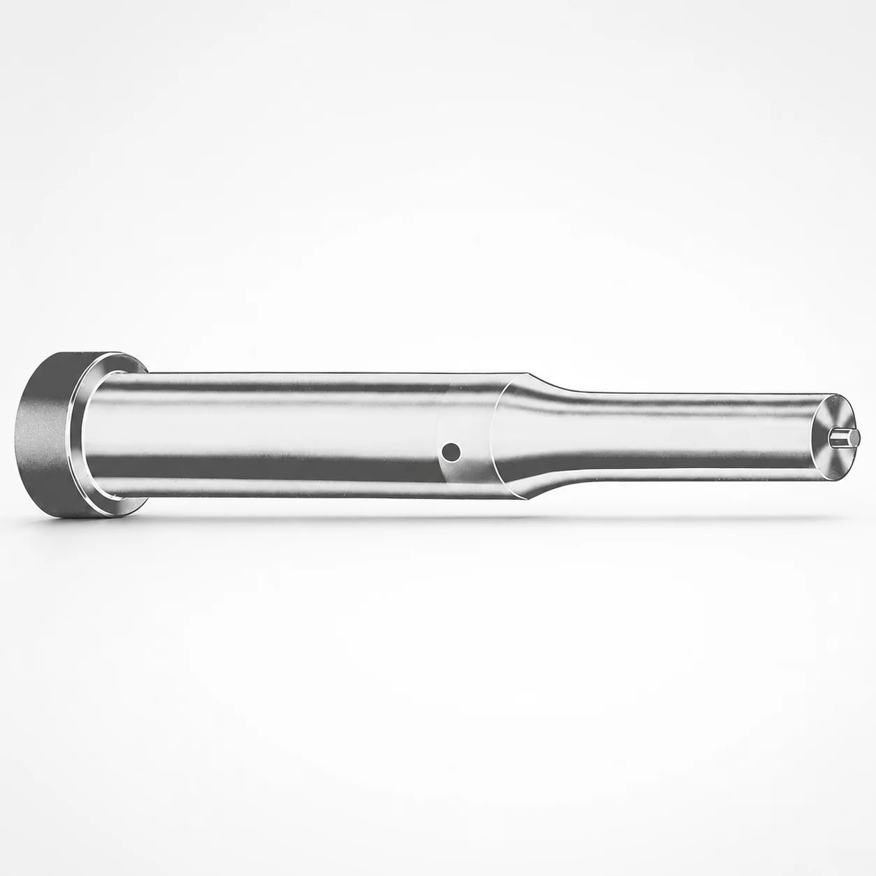
Ejector Punches Inch XCD Coating
Ejector Punches Inch (XCD Coating) are designed for reliable punch performance in die and mold fabrication, supporting consistent fit and stable production results. The XCD coating helps improve surface durability under demanding cycles.
- Inch ejector punch geometry with selectable tip shape options for tool fit
- XCD coating supports wear and surface protection in high-cycle forming
- Supports selection by coded point length and shank diameter ranges
- Compatible with press and die work where punch wear resistance matters
Specifications
750 configurations available
| Tip shape | D (Shank dia.) (in) | Jektole group | Standard [S] Point Length B & L (Length) (coded inch) | Alternate [B] Point Length B & L (Length) (coded inch) | Alternate [C] Point Length B & L (Length) (coded inch) | Alternate [D] Point Length B & L (Length) (coded inch) | Alternate [E] Point Length B & L (Length) (coded inch) | P Dimension (in) | W Dimension (in) | R Dimension (in) |
|---|---|---|---|---|---|---|---|---|---|---|
| H | 18(0.1875") | J2 | - | 150 ~ 400 | - | - | - | 0.062 ~ 0.1875 | 0.062 ~ 0.1875 | - |
| H | 18(0.1875") | J2 | 150 ~ 400 | - | - | - | - | 0.062 ~ 0.1875 | 0.062 ~ 0.1875 | - |
| H | 25(0.2500") | J3 | - | 150 ~ 400 | - | - | - | 0.08 ~ 0.25 | 0.08 ~ 0.0929 | - |
| H | 25(0.2500") | J3 | - | 150 ~ 400 | - | - | - | 0.08 ~ 0.25 | 0.093 ~ 0.25 | - |
| H | 25(0.2500") | J3 | 150 ~ 400 | - | - | - | - | 0.08 ~ 0.25 | 0.08 ~ 0.0929 | - |
| H | 25(0.2500") | J3 | 150 ~ 400 | - | - | - | - | 0.08 ~ 0.25 | 0.093 ~ 0.25 | - |
| H | 31(0.3125") | J4 | - | 150 ~ 600 | - | - | - | 0.115 ~ 0.3125 | 0.115 ~ 0.1249 | - |
| H | 31(0.3125") | J4 | - | 150 ~ 600 | - | - | - | 0.115 ~ 0.3125 | 0.125 ~ 0.3125 | - |
| H | 31(0.3125") | J4 | - | - | 175 ~ 600 | - | - | 0.115 ~ 0.3125 | 0.115 ~ 0.1249 | - |
| H | 31(0.3125") | J4 | - | - | 175 ~ 600 | - | - | 0.115 ~ 0.3125 | 0.125 ~ 0.3125 | - |
| H | 31(0.3125") | J4 | 150 ~ 600 | - | - | - | - | 0.115 ~ 0.3125 | 0.115 ~ 0.1249 | - |
| H | 31(0.3125") | J4 | 150 ~ 600 | - | - | - | - | 0.115 ~ 0.3125 | 0.125 ~ 0.3125 | - |
| H | 37(0.3750") | J6 | - | 175 ~ 625 | - | - | - | 0.158 ~ 0.375 | 0.158 ~ 0.1869 | - |
| H | 37(0.3750") | J6 | - | 175 ~ 625 | - | - | - | 0.158 ~ 0.375 | 0.187 ~ 0.375 | - |
| H | 37(0.3750") | J6 | - | - | 175 ~ 625 | - | - | 0.158 ~ 0.375 | 0.158 ~ 0.1869 | - |
| H | 37(0.3750") | J6 | - | - | 175 ~ 625 | - | - | 0.158 ~ 0.375 | 0.187 ~ 0.375 | - |
| H | 37(0.3750") | J6 | 175 ~ 625 | - | - | - | - | 0.158 ~ 0.375 | 0.158 ~ 0.1869 | - |
| H | 37(0.3750") | J6 | 175 ~ 625 | - | - | - | - | 0.158 ~ 0.375 | 0.187 ~ 0.375 | - |
| H | 43(0.4375") | J6 | - | - | 200 ~ 625 | - | - | 0.158 ~ 0.4375 | 0.158 ~ 0.1869 | - |
| H | 43(0.4375") | J6 | - | - | 200 ~ 625 | - | - | 0.158 ~ 0.4375 | 0.187 ~ 0.4375 | - |
| H | 43(0.4375") | J6 | 200 ~ 625 | - | - | - | - | 0.158 ~ 0.4375 | 0.158 ~ 0.1869 | - |
| H | 43(0.4375") | J6 | 200 ~ 625 | - | - | - | - | 0.158 ~ 0.4375 | 0.187 ~ 0.4375 | - |
| H | 50(0.5000") | J6 | - | - | 200 ~ 625 | - | - | 0.158 ~ 0.5 | 0.158 ~ 0.1869 | - |
| H | 50(0.5000") | J6 | - | - | 200 ~ 625 | - | - | 0.158 ~ 0.5 | 0.187 ~ 0.5 | - |
| H | 50(0.5000") | J6 | 200 ~ 625 | - | - | - | - | 0.158 ~ 0.5 | 0.158 ~ 0.1869 | - |
| H | 50(0.5000") | J6 | 200 ~ 625 | - | - | - | - | 0.158 ~ 0.5 | 0.187 ~ 0.5 | - |
| H | 62(0.6250") | J9 | - | - | - | 225 ~ 625 | - | 0.235 ~ 0.625 | 0.25 ~ 0.625 | - |
| H | 62(0.6250") | J9 | - | - | - | 225 ~ 625 | - | 0.235 ~ 0.625 | 0.235 ~ 0.2499 | - |
| H | 62(0.6250") | J9 | 225 ~ 625 | - | - | - | - | 0.235 ~ 0.625 | 0.25 ~ 0.625 | - |
| H | 62(0.6250") | J9 | 225 ~ 625 | - | - | - | - | 0.235 ~ 0.625 | 0.235 ~ 0.2499 | - |
| H | 75(0.7500") | J9 | - | - | - | 225 ~ 625 | - | 0.235 ~ 0.75 | 0.235 ~ 0.3119 | - |
| H | 75(0.7500") | J9 | - | - | - | 225 ~ 625 | - | 0.235 ~ 0.75 | 0.312 ~ 0.75 | - |
| H | 75(0.7500") | J9 | 225 ~ 625 | - | - | - | - | 0.235 ~ 0.75 | 0.235 ~ 0.3119 | - |
| H | 75(0.7500") | J9 | 225 ~ 625 | - | - | - | - | 0.235 ~ 0.75 | 0.312 ~ 0.75 | - |
| H | 87(0.8750") | J9 | - | - | - | 225 ~ 650 | - | 0.235 ~ 0.875 | 0.235 ~ 0.3119 | - |
| H | 87(0.8750") | J9 | - | - | - | 225 ~ 650 | - | 0.235 ~ 0.875 | 0.312 ~ 0.875 | - |
| H | 87(0.8750") | J9 | - | - | - | - | 225 ~ 650 | 0.235 ~ 0.875 | 0.235 ~ 0.3119 | - |
| H | 87(0.8750") | J9 | - | - | - | - | 225 ~ 650 | 0.235 ~ 0.875 | 0.312 ~ 0.875 | - |
| H | 87(0.8750") | J9 | 225 ~ 650 | - | - | - | - | 0.235 ~ 0.875 | 0.235 ~ 0.3119 | - |
| H | 87(0.8750") | J9 | 225 ~ 650 | - | - | - | - | 0.235 ~ 0.875 | 0.312 ~ 0.875 | - |
| H | 100(1.0000") | J9 | - | - | - | - | 250 ~ 650 | 0.235 ~ 1 | 0.235 ~ 0.3119 | - |
| H | 100(1.0000") | J9 | - | - | - | - | 250 ~ 650 | 0.235 ~ 1 | 0.312 ~ 1 | - |
| H | 100(1.0000") | J9 | 250 ~ 650 | - | - | - | - | 0.235 ~ 1 | 0.235 ~ 0.3119 | - |
| H | 100(1.0000") | J9 | 250 ~ 650 | - | - | - | - | 0.235 ~ 1 | 0.312 ~ 1 | - |
| H | 125(1.2500") | J12 | - | - | - | - | 250 ~ 700 | 0.281 ~ 1.25 | 0.281 ~ 0.3119 | - |
| H | 125(1.2500") | J12 | - | - | - | - | 250 ~ 700 | 0.281 ~ 1.25 | 0.312 ~ 1.25 | - |
| H | 125(1.2500") | J12 | 250 ~ 700 | - | - | - | - | 0.281 ~ 1.25 | 0.281 ~ 0.3119 | - |
| H | 125(1.2500") | J12 | 250 ~ 700 | - | - | - | - | 0.281 ~ 1.25 | 0.312 ~ 1.25 | - |
| H | 150(1.5000") | J12 | - | - | - | - | 250 ~ 700 | 0.281 ~ 1.5 | 0.281 ~ 0.3119 | - |
| H | 150(1.5000") | J12 | - | - | - | - | 250 ~ 700 | 0.281 ~ 1.5 | 0.312 ~ 1.5 | - |
Product Guide
Application Scenarios+
Ejector punches with XCD coating are used in injection and die tooling where punch surfaces repeatedly rub, strike, or slide under high duty cycles. The inch-based geometry and selectable tip shapes (H, J, K, L, N, O, R, V, X, Y, Z) make them a practical fit for specific ejector pin/punch layouts and press operations.
- Automotive and industrial die casting: suitable for post-forming punch-through and component ejection routines where the coating helps protect the working surface against cycle-to-cycle wear, supporting consistent dimensional behavior.
- Precision punch stations: when toolmakers need stable fit at the shank and a controlled point profile, the XCD layer improves surface durability during frequent forming/punching operations.
- High-cycle forming inserts: ideal for applications where abrasion and surface damage limit punch life; selecting the correct point length group and shank diameter range helps maintain effective travel and alignment.
Material & Process Details+
The provided specifications describe an inch ejector punch configuration with XCD coating, but no base steel grade, heat-treatment state, or hardness (HRC) values are listed in the data. Therefore, the material properties and tempering/nitriding details for the underlying punch steel cannot be confirmed from the current dataset.
- XCD coating purpose: designed to improve surface durability and wear resistance under demanding, high-cycle punch activity, helping reduce surface degradation that can affect fit and finish.
- Trade-offs: coating systems typically balance harder surface protection with the need to maintain toughness at the substrate; selecting the correct point length and shank diameter is essential to avoid bending or misalignment loads.
- Material comparison note: if alternate base materials are offered by the manufacturer, they should be selected based on your hardness and toughness targets; request the base steel specification to finalize heat-treatment expectations.
Sizing & Selection Guide+
Select dimensions by matching your ejector/cavity engagement geometry to the punch shank diameter and point length codes. For shank diameter, use the available range D = 18 ~ 250 in (per the provided parameter). For working engagement length, pick the standard [S] point length coded option 150 ~ 250 (inch code range), or choose an alternate coded set depending on the required protrusion and clearance.
- Point length options: Alternate [B]: 150 ~ 400, 150 ~ 600, or 175 ~ 625; Alternate [C]: 175 ~ 600, 175 ~ 625, or 200 ~ 625; Alternate [D]: 225 ~ 625 or 225 ~ 650; Alternate [E]: 225 ~ 650, 250 ~ 650, or 250 ~ 700.
- Profile sizing: verify tip shape (H, J, K, L, N, O, R, V, X, Y, Z) matches the die/punch contact envelope.
- Engagement geometry: confirm P and W dimensions (P = 0.05 ~ 1.625 in, W = 0.062 ~ 0.5 in) and R (R = 0.007 ~ 0.007 in) align with your required radii and edge breaks.
Frequently Asked Questions
Which tip shapes (H, J, K, L, N, O, R, V, X, Y, Z) should I consider for different punch contact geometries?+
How do I select the correct coded point length for adequate ejector travel?+
What shank diameter range (D) is available for this ejector punch series?+
Does the XCD coating improve wear resistance in high-cycle punch and die operations?+
How do P, W, and R dimensions affect fit to the die pocket or point contact area?+
Related Products






Need Custom Specifications?
Our engineering team can help with custom configurations, material selection, and volume pricing.