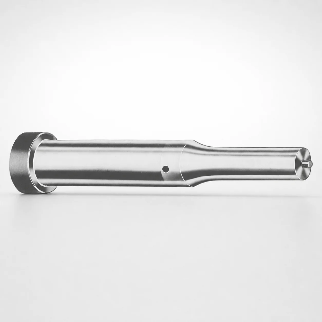
Inch Ejector Punches - CRN Coating
Inch ejector punches - CRN coating are designed for stable part ejection in progressive and tooling applications, combining Dayton Lamina standardized part formatting with a wear-focused CRN surface. They help reduce downtime from abrasion during repeated cycles.
- Inch-size ejector punch geometry for consistent ejection in tooling
- CRN coating improves wear resistance for long cycle life
- Supports selection of tip shapes (optional) for matched engagement
- Standardized part format helps streamline ordering and compatibility checks
Specifications
750 configurations available
| Tip shape | D (Shank dia.) (in) | Jektole group | Standard [S] Point Length B & L (Length) (coded inch) | Alternate [B] Point Length B & L (Length) (coded inch) | Alternate [C] Point Length B & L (Length) (coded inch) | Alternate [D] Point Length B & L (Length) (coded inch) | Alternate [E] Point Length B & L (Length) (coded inch) | P Dimension (in) | W Dimension (in) | R Dimension (in) |
|---|---|---|---|---|---|---|---|---|---|---|
| H | 18(0.1875") | J2 | - | 150 ~ 400 | - | - | - | 0.062 ~ 0.1875 | 0.062 ~ 0.1875 | - |
| H | 18(0.1875") | J2 | 150 ~ 400 | - | - | - | - | 0.062 ~ 0.1875 | 0.062 ~ 0.1875 | - |
| H | 25(0.2500") | J3 | - | 150 ~ 400 | - | - | - | 0.08 ~ 0.25 | 0.08 ~ 0.0929 | - |
| H | 25(0.2500") | J3 | - | 150 ~ 400 | - | - | - | 0.08 ~ 0.25 | 0.093 ~ 0.25 | - |
| H | 25(0.2500") | J3 | 150 ~ 400 | - | - | - | - | 0.08 ~ 0.25 | 0.08 ~ 0.0929 | - |
| H | 25(0.2500") | J3 | 150 ~ 400 | - | - | - | - | 0.08 ~ 0.25 | 0.093 ~ 0.25 | - |
| H | 31(0.3125") | J4 | - | 150 ~ 600 | - | - | - | 0.115 ~ 0.3125 | 0.115 ~ 0.1249 | - |
| H | 31(0.3125") | J4 | - | 150 ~ 600 | - | - | - | 0.115 ~ 0.3125 | 0.125 ~ 0.3125 | - |
| H | 31(0.3125") | J4 | - | - | 175 ~ 600 | - | - | 0.115 ~ 0.3125 | 0.115 ~ 0.1249 | - |
| H | 31(0.3125") | J4 | - | - | 175 ~ 600 | - | - | 0.115 ~ 0.3125 | 0.125 ~ 0.3125 | - |
| H | 31(0.3125") | J4 | 150 ~ 600 | - | - | - | - | 0.115 ~ 0.3125 | 0.115 ~ 0.1249 | - |
| H | 31(0.3125") | J4 | 150 ~ 600 | - | - | - | - | 0.115 ~ 0.3125 | 0.125 ~ 0.3125 | - |
| H | 37(0.3750") | J6 | - | 175 ~ 625 | - | - | - | 0.158 ~ 0.375 | 0.158 ~ 0.1869 | - |
| H | 37(0.3750") | J6 | - | 175 ~ 625 | - | - | - | 0.158 ~ 0.375 | 0.187 ~ 0.375 | - |
| H | 37(0.3750") | J6 | - | - | 175 ~ 625 | - | - | 0.158 ~ 0.375 | 0.158 ~ 0.1869 | - |
| H | 37(0.3750") | J6 | - | - | 175 ~ 625 | - | - | 0.158 ~ 0.375 | 0.187 ~ 0.375 | - |
| H | 37(0.3750") | J6 | 175 ~ 625 | - | - | - | - | 0.158 ~ 0.375 | 0.158 ~ 0.1869 | - |
| H | 37(0.3750") | J6 | 175 ~ 625 | - | - | - | - | 0.158 ~ 0.375 | 0.187 ~ 0.375 | - |
| H | 43(0.4375") | J6 | - | - | 200 ~ 625 | - | - | 0.158 ~ 0.4375 | 0.158 ~ 0.1869 | - |
| H | 43(0.4375") | J6 | - | - | 200 ~ 625 | - | - | 0.158 ~ 0.4375 | 0.187 ~ 0.4375 | - |
| H | 43(0.4375") | J6 | 200 ~ 625 | - | - | - | - | 0.158 ~ 0.4375 | 0.158 ~ 0.1869 | - |
| H | 43(0.4375") | J6 | 200 ~ 625 | - | - | - | - | 0.158 ~ 0.4375 | 0.187 ~ 0.4375 | - |
| H | 50(0.5000") | J6 | - | - | 200 ~ 625 | - | - | 0.158 ~ 0.5 | 0.158 ~ 0.1869 | - |
| H | 50(0.5000") | J6 | - | - | 200 ~ 625 | - | - | 0.158 ~ 0.5 | 0.187 ~ 0.5 | - |
| H | 50(0.5000") | J6 | 200 ~ 625 | - | - | - | - | 0.158 ~ 0.5 | 0.158 ~ 0.1869 | - |
| H | 50(0.5000") | J6 | 200 ~ 625 | - | - | - | - | 0.158 ~ 0.5 | 0.187 ~ 0.5 | - |
| H | 62(0.6250") | J9 | - | - | - | 225 ~ 625 | - | 0.235 ~ 0.625 | 0.25 ~ 0.625 | - |
| H | 62(0.6250") | J9 | - | - | - | 225 ~ 625 | - | 0.235 ~ 0.625 | 0.235 ~ 0.2499 | - |
| H | 62(0.6250") | J9 | 225 ~ 625 | - | - | - | - | 0.235 ~ 0.625 | 0.25 ~ 0.625 | - |
| H | 62(0.6250") | J9 | 225 ~ 625 | - | - | - | - | 0.235 ~ 0.625 | 0.235 ~ 0.2499 | - |
| H | 75(0.7500") | J9 | - | - | - | 225 ~ 625 | - | 0.235 ~ 0.75 | 0.235 ~ 0.3119 | - |
| H | 75(0.7500") | J9 | - | - | - | 225 ~ 625 | - | 0.235 ~ 0.75 | 0.312 ~ 0.75 | - |
| H | 75(0.7500") | J9 | 225 ~ 625 | - | - | - | - | 0.235 ~ 0.75 | 0.235 ~ 0.3119 | - |
| H | 75(0.7500") | J9 | 225 ~ 625 | - | - | - | - | 0.235 ~ 0.75 | 0.312 ~ 0.75 | - |
| H | 87(0.8750") | J9 | - | - | - | 225 ~ 650 | - | 0.235 ~ 0.875 | 0.235 ~ 0.3119 | - |
| H | 87(0.8750") | J9 | - | - | - | 225 ~ 650 | - | 0.235 ~ 0.875 | 0.312 ~ 0.875 | - |
| H | 87(0.8750") | J9 | - | - | - | - | 225 ~ 650 | 0.235 ~ 0.875 | 0.235 ~ 0.3119 | - |
| H | 87(0.8750") | J9 | - | - | - | - | 225 ~ 650 | 0.235 ~ 0.875 | 0.312 ~ 0.875 | - |
| H | 87(0.8750") | J9 | 225 ~ 650 | - | - | - | - | 0.235 ~ 0.875 | 0.235 ~ 0.3119 | - |
| H | 87(0.8750") | J9 | 225 ~ 650 | - | - | - | - | 0.235 ~ 0.875 | 0.312 ~ 0.875 | - |
| H | 100(1.0000") | J9 | - | - | - | - | 250 ~ 650 | 0.235 ~ 1 | 0.235 ~ 0.3119 | - |
| H | 100(1.0000") | J9 | - | - | - | - | 250 ~ 650 | 0.235 ~ 1 | 0.312 ~ 1 | - |
| H | 100(1.0000") | J9 | 250 ~ 650 | - | - | - | - | 0.235 ~ 1 | 0.235 ~ 0.3119 | - |
| H | 100(1.0000") | J9 | 250 ~ 650 | - | - | - | - | 0.235 ~ 1 | 0.312 ~ 1 | - |
| H | 125(1.2500") | J12 | - | - | - | - | 250 ~ 700 | 0.281 ~ 1.25 | 0.281 ~ 0.3119 | - |
| H | 125(1.2500") | J12 | - | - | - | - | 250 ~ 700 | 0.281 ~ 1.25 | 0.312 ~ 1.25 | - |
| H | 125(1.2500") | J12 | 250 ~ 700 | - | - | - | - | 0.281 ~ 1.25 | 0.281 ~ 0.3119 | - |
| H | 125(1.2500") | J12 | 250 ~ 700 | - | - | - | - | 0.281 ~ 1.25 | 0.312 ~ 1.25 | - |
| H | 150(1.5000") | J12 | - | - | - | - | 250 ~ 700 | 0.281 ~ 1.5 | 0.281 ~ 0.3119 | - |
| H | 150(1.5000") | J12 | - | - | - | - | 250 ~ 700 | 0.281 ~ 1.5 | 0.312 ~ 1.5 | - |
Product Guide
Application Scenarios+
Inch ejector punches with a CRN surface coating are used in injection and press tooling where parts must be reliably stripped from cavities after each cycle. They are well-suited for progressive tooling stations and high-fidelity forming/die service because the CRN-coated punch bodies help maintain a stable contact surface under repeated metal-to-tool engagement.
- Automotive and industrial connector housings: Use these ejectors in multi-cavity progressive inserts to stabilize ejection during long production runs where abrasive wear can otherwise cause ejection drag and inconsistent part release.
- Appliance and metal forming dies: Choose the CRN variant when ejectors see frequent wiping/contact against die steel; the coating supports longer cycle life compared with uncoated punches.
- Medical device component tooling (small molded parts): Select the appropriate tip shape and point length range to match limited clearances while keeping ejection consistent across steady-state cycling.
Choose the specific tip shape option (H, J, K, L, N, O, R, V, X, Y, Z) to ensure matched engagement with the part geometry and ejection force path.
Material & Process Details+
The CRN-coated punch bodies are engineered to improve wear resistance at the working surface, which is critical for ejector components exposed to repeated sliding and abrasion during ejection cycles. While the base steel grade is not specified in the provided data, the process intent is clear: a hard, wear-focused CRN layer on the shank/working area to reduce surface degradation and help maintain dimensional stability over time.
- Heat treatment state: The product specification provided does not list a specific steel grade or hardness (HRC) value; therefore hardness and exact tempering steps cannot be confirmed from the available information.
- Wear vs. toughness trade-off: CRN coatings prioritize surface hardness and abrasion resistance, which generally benefits ejection durability; however, coating performance depends on correct tip geometry and alignment to avoid edge chipping.
- Coating comparison: Compared with uncoated ejector punches, CRN variants typically reduce abrasive wear and support longer cycle life in tooling with persistent contact.
Sizing & Selection Guide+
Select dimensions by matching your ejector travel, engagement length, and shank fit to the mold’s ejector system and cavity/core clearance. This series provides flexible configuration through tip shape and multiple length coding ranges.
- Shank diameter (D): Choose from 18 ~ 250 (in) to match the ejector guide bore and support requirements in your tooling design.
- Point length (B & L): Use the standard S range 150 ~ 250 (coded inch), or select alternate options depending on reach needs: 150 ~ 400, 150 ~ 600, 175 ~ 625, 200 ~ 625, 225 ~ 625, 225 ~ 650, 250 ~ 650, or 250 ~ 700 (coded inch ranges are tied to alternate groupings).
- Engagement dimensions: Confirm P (0.05 ~ 1.625) and W (0.062 ~ 0.5) as they influence contact area and ejection stability; R is specified as 0.007.
For best fit, coordinate the selected tip shape and point length with the cavity/core feature depth and any draft or undercut clearance to prevent over-penetration or side loading.
Frequently Asked Questions
Which tip shapes (H, J, K, L, N, O, R, V, X, Y, Z) should I choose for stable ejector engagement?+
Tip shape selection is intended to match your part’s contact geometry and the ejection force path. This series supports multiple tip shapes: H, J, K, L, N, O, R, V, X, Y, Z, so you can align the working end to the cavity/core clearance and part form to reduce side loading during cycles.
Choose the tip shape together with the point length range (B & L coded inch) to ensure the punch reaches the needed ejection travel without excessive penetration.
What shank diameter range (D) is available for these inch ejector punches?+
The available shank diameter (D) range for this series is 18 ~ 250 (in). Select D based on your ejector bore and guidance fit in the mold base and ejector plate.
Use the shank diameter to ensure adequate support and alignment so the coated working surface contacts the part without inducing deflection.
How do I pick the correct point length (B & L) coded inch range for my mold cavity depth?+
The series provides a standard S point length range of 150 ~ 250 (coded inch). It also offers multiple alternate B & L ranges such as 150 ~ 400, 150 ~ 600, 175 ~ 625, 200 ~ 625, 225 ~ 625, 225 ~ 650, 250 ~ 650, and 250 ~ 700 depending on the configured grouping.
Match the selected coded point length to the required engagement depth and clearance in the cavity/core so you achieve consistent ejection without bottoming out.
What are the available control dimensions P, W, and the R value for this CRN-coated ejector punch series?+
This series specifies P = 0.05 ~ 1.625 (in), W = 0.062 ~ 0.5 (in), and R = 0.007. These dimensions affect the local geometry of the working end that interfaces with the part.
When confirming fit, validate these geometry values against the part’s contact area and the cavity/core feature to prevent excessive contact pressure or misalignment.
Do I need a specific Jektole group (J2, J3, J4, J6, J9, J12) to match mold compatibility?+
The metadata lists selectable Jektole group options: J2, J3, J4, J6, J9, J12. This grouping typically helps define standardized configuration sets for the punch geometry and associated length coding.
For compatibility, choose the group together with the required tip shape and point length range (S or alternates) so the punch reaches the intended ejection engagement within your tooling constraints.
Related Products






Need Custom Specifications?
Our engineering team can help with custom configurations, material selection, and volume pricing.