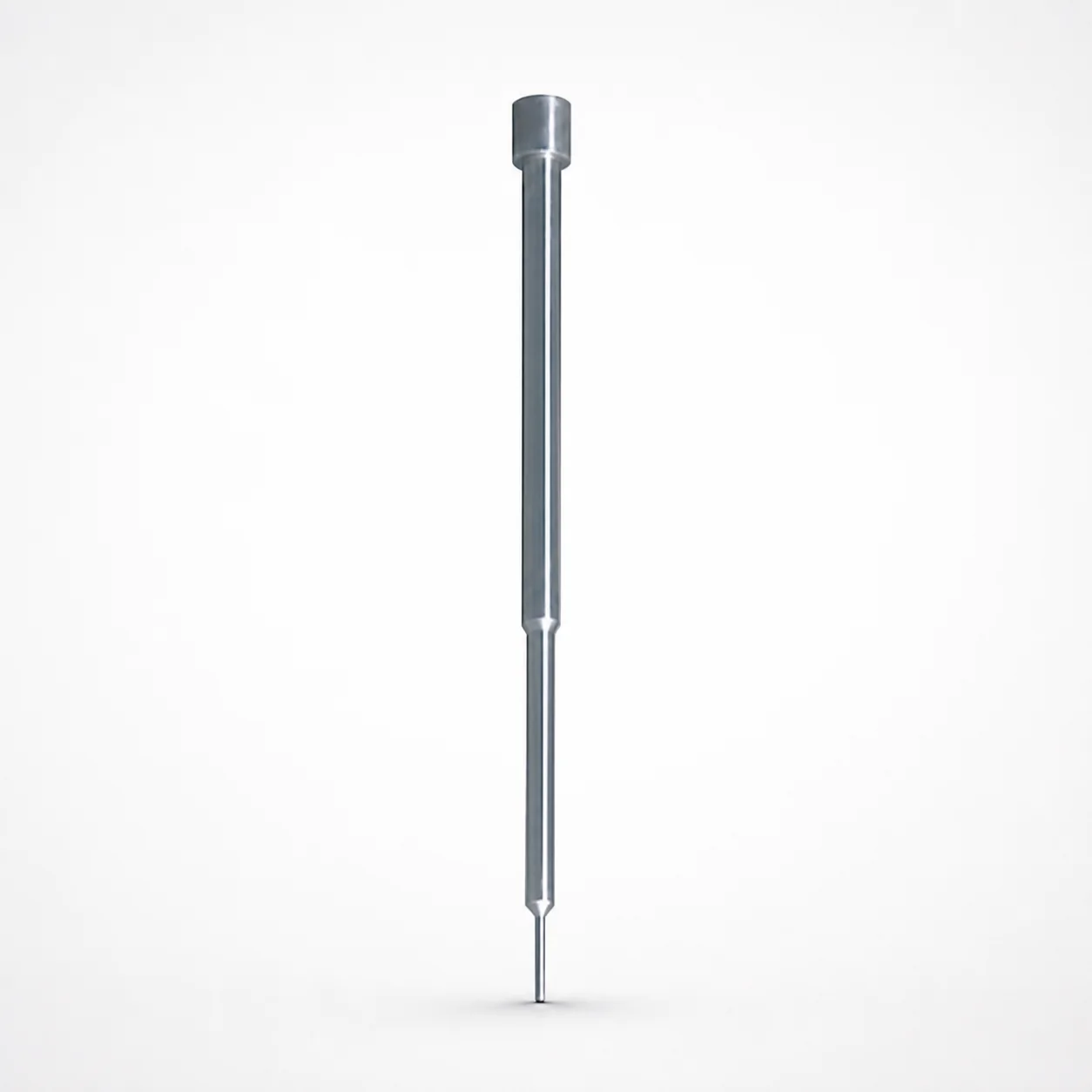
Double Stepped Quill Shoulder Punches
Double Stepped Quill Shoulder Punches (SKH51/M2 hardened steel options) provide reliable precision for heavy-load punching. The double-stepped shank supports stable guiding, helping maintain consistent punching performance while improving punch life.
- Double-stepped quill shank for stable positioning under heavy-duty cycles
- Durable SKH51/M2 hardened steel construction for wear resistance
- Designed to support tight shank fit with m5 tolerance reference
- Suitable for progressive tooling and high-efficiency industrial stamping applications
Specifications
48 configurations available
| Material | Shank diameter D tolerance | D (Shank diameter) (mm) | P (Tip dimension) (mm) | L (L dimension) (mm) | B (Tip length) (mm) | F (Length from tip end to second step R) (mm) | LC (Full length alteration) (mm) | LCT (Head thickness tolerance change + Total length alteration) (mm) | LMT (Head thickness tolerance change + Total length alteration) (mm) | V (Second step tip diameter) (mm) | type |
|---|---|---|---|---|---|---|---|---|---|---|---|
| SKH40 Equivalent (Powdered High-Speed Steel) | +0.005/0 | 1.6 | 0.3 ~ 1.56 | 20 ~ 50 | 1 ~ 10 | 2 ~ 20 | - | - | - | 0.31 ~ 1.59 | - |
| SKH40 Equivalent (Powdered High-Speed Steel) | +0.005/0 | 1.6 | 0.3 ~ 1.56 | - | 1 ~ 10 | 2 ~ 20 | 20 ~ 59.9 | - | - | 0.31 ~ 1.59 | - |
| SKH40 Equivalent (Powdered High-Speed Steel) | +0.005/0 | 1.6 | 0.3 ~ 1.56 | - | 1 ~ 10 | 2 ~ 20 | - | - | - | 0.31 ~ 1.59 | - |
| SKH40 Equivalent (Powdered High-Speed Steel) | +0.005/0 | 1.6 | 0.3 ~ 1.56 | - | 1 ~ 10 | 2 ~ 20 | - | - | 20 ~ 59.9 | 0.31 ~ 1.59 | - |
| SKH40 Equivalent (Powdered High-Speed Steel) | +0.005/0 | 2.0 | 0.5 ~ 1.96 | 20 ~ 50 | 1 ~ 10 | 2 ~ 20 | - | - | - | 0.51 ~ 1.99 | - |
| SKH40 Equivalent (Powdered High-Speed Steel) | +0.005/0 | 2.0 | 0.5 ~ 1.96 | - | 1 ~ 10 | 2 ~ 20 | 20 ~ 59.9 | - | - | 0.51 ~ 1.99 | - |
| SKH40 Equivalent (Powdered High-Speed Steel) | +0.005/0 | 2.0 | 0.5 ~ 1.96 | - | 1 ~ 10 | 2 ~ 20 | - | - | - | 0.51 ~ 1.99 | - |
| SKH40 Equivalent (Powdered High-Speed Steel) | +0.005/0 | 2.0 | 0.5 ~ 1.96 | - | 1 ~ 10 | 2 ~ 20 | - | - | 20 ~ 59.9 | 0.51 ~ 1.99 | - |
| SKH40 Equivalent (Powdered High-Speed Steel) | +0.005/0 | 2.5 | 0.8 ~ 2.46 | 20 ~ 50 | 1 ~ 10 | 2 ~ 35 | - | - | - | 0.51 ~ 2.99 | - |
| SKH40 Equivalent (Powdered High-Speed Steel) | +0.005/0 | 2.5 | 0.8 ~ 2.46 | - | 1 ~ 10 | 2 ~ 35 | 20 ~ 59.9 | - | - | 0.51 ~ 2.99 | - |
| SKH40 Equivalent (Powdered High-Speed Steel) | +0.005/0 | 2.5 | 0.8 ~ 2.46 | - | 1 ~ 10 | 2 ~ 35 | - | - | - | 0.51 ~ 2.99 | - |
| SKH40 Equivalent (Powdered High-Speed Steel) | +0.005/0 | 2.5 | 0.8 ~ 2.46 | - | 1 ~ 10 | 2 ~ 35 | - | - | 20 ~ 59.9 | 0.51 ~ 2.99 | - |
| SKH51 Equivalent (M2) | +0.005/0 | 1.6 | 0.3 ~ 1.56 | 20 ~ 50 | 1 ~ 10 | 2 ~ 20 | - | - | - | 0.31 ~ 1.59 | - |
| SKH51 Equivalent (M2) | +0.005/0 | 1.6 | 0.3 ~ 1.56 | - | 1 ~ 10 | 2 ~ 20 | 20 ~ 59.9 | - | - | 0.31 ~ 1.59 | - |
| SKH51 Equivalent (M2) | +0.005/0 | 1.6 | 0.3 ~ 1.56 | - | 1 ~ 10 | 2 ~ 20 | - | - | - | 0.31 ~ 1.59 | - |
| SKH51 Equivalent (M2) | +0.005/0 | 1.6 | 0.3 ~ 1.56 | - | 1 ~ 10 | 2 ~ 20 | - | - | 20 ~ 59.9 | 0.31 ~ 1.59 | - |
| SKH51 Equivalent (M2) | +0.005/0 | 2.0 | 0.5 ~ 1.96 | 20 ~ 50 | 1 ~ 10 | 2 ~ 20 | - | - | - | 0.51 ~ 1.99 | - |
| SKH51 Equivalent (M2) | +0.005/0 | 2.0 | 0.5 ~ 1.96 | - | 1 ~ 10 | 2 ~ 20 | 20 ~ 59.9 | - | - | 0.51 ~ 1.99 | - |
| SKH51 Equivalent (M2) | +0.005/0 | 2.0 | 0.5 ~ 1.96 | - | 1 ~ 10 | 2 ~ 20 | - | - | - | 0.51 ~ 1.99 | - |
| SKH51 Equivalent (M2) | +0.005/0 | 2.0 | 0.5 ~ 1.96 | - | 1 ~ 10 | 2 ~ 20 | - | - | 20 ~ 59.9 | 0.51 ~ 1.99 | - |
| SKH51 Equivalent (M2) | +0.005/0 | 2.5 | 0.8 ~ 2.46 | 20 ~ 50 | 1 ~ 10 | 2 ~ 35 | - | - | - | 0.51 ~ 2.99 | - |
| SKH51 Equivalent (M2) | +0.005/0 | 2.5 | 0.8 ~ 2.46 | - | 1 ~ 10 | 2 ~ 35 | 20 ~ 59.9 | - | - | 0.51 ~ 2.99 | - |
| SKH51 Equivalent (M2) | +0.005/0 | 2.5 | 0.8 ~ 2.46 | - | 1 ~ 10 | 2 ~ 35 | - | - | - | 0.51 ~ 2.99 | - |
| SKH51 Equivalent (M2) | +0.005/0 | 2.5 | 0.8 ~ 2.46 | - | 1 ~ 10 | 2 ~ 35 | - | - | 20 ~ 59.9 | 0.51 ~ 2.99 | - |
| SKH40 Equivalent (Powdered High-Speed Steel) | m5 | 1.6 | 0.3 ~ 1.56 | 20 ~ 60 | 1 ~ 10 | 2 ~ 20 | - | - | - | 0.31 ~ 1.59 | - |
| SKH40 Equivalent (Powdered High-Speed Steel) | m5 | 1.6 | 0.3 ~ 1.56 | - | 1 ~ 10 | 2 ~ 20 | 20 ~ 59.9 | - | - | 0.31 ~ 1.59 | - |
| SKH40 Equivalent (Powdered High-Speed Steel) | m5 | 1.6 | 0.3 ~ 1.56 | - | 1 ~ 10 | 2 ~ 20 | - | 20 ~ 59.9 | - | 0.31 ~ 1.59 | - |
| SKH40 Equivalent (Powdered High-Speed Steel) | m5 | 1.6 | 0.3 ~ 1.56 | - | 1 ~ 10 | 2 ~ 20 | - | - | 20 ~ 49.9 | 0.31 ~ 1.59 | - |
| SKH40 Equivalent (Powdered High-Speed Steel) | m5 | 2.0 | 0.5 ~ 1.96 | 20 ~ 60 | 1 ~ 10 | 2 ~ 20 | - | - | - | 0.51 ~ 1.99 | - |
| SKH40 Equivalent (Powdered High-Speed Steel) | m5 | 2.0 | 0.5 ~ 1.96 | - | 1 ~ 10 | 2 ~ 20 | 20 ~ 59.9 | - | - | 0.51 ~ 1.99 | - |
| SKH40 Equivalent (Powdered High-Speed Steel) | m5 | 2.0 | 0.5 ~ 1.96 | - | 1 ~ 10 | 2 ~ 20 | - | 20 ~ 59.9 | - | 0.51 ~ 1.99 | - |
| SKH40 Equivalent (Powdered High-Speed Steel) | m5 | 2.0 | 0.5 ~ 1.96 | - | 1 ~ 10 | 2 ~ 20 | - | - | 20 ~ 49.9 | 0.51 ~ 1.99 | - |
| SKH40 Equivalent (Powdered High-Speed Steel) | m5 | 2.5 | 0.8 ~ 2.46 | 20 ~ 60 | 1 ~ 10 | 2 ~ 35 | - | - | - | 0.51 ~ 2.99 | - |
| SKH40 Equivalent (Powdered High-Speed Steel) | m5 | 2.5 | 0.8 ~ 2.46 | - | 1 ~ 10 | 2 ~ 35 | 20 ~ 59.9 | - | - | 0.51 ~ 2.99 | - |
| SKH40 Equivalent (Powdered High-Speed Steel) | m5 | 2.5 | 0.8 ~ 2.46 | - | 1 ~ 10 | 2 ~ 35 | - | 20 ~ 59.9 | - | 0.51 ~ 2.99 | - |
| SKH40 Equivalent (Powdered High-Speed Steel) | m5 | 2.5 | 0.8 ~ 2.46 | - | 1 ~ 10 | 2 ~ 35 | - | - | 20 ~ 49.9 | 0.51 ~ 2.99 | - |
| SKH51 Equivalent (M2) | m5 | 1.6 | 0.3 ~ 1.56 | 20 ~ 60 | 1 ~ 10 | 2 ~ 20 | - | - | - | 0.31 ~ 1.59 | - |
| SKH51 Equivalent (M2) | m5 | 1.6 | 0.3 ~ 1.56 | - | 1 ~ 10 | 2 ~ 20 | 20 ~ 59.9 | - | - | 0.31 ~ 1.59 | - |
| SKH51 Equivalent (M2) | m5 | 1.6 | 0.3 ~ 1.56 | - | 1 ~ 10 | 2 ~ 20 | - | 20 ~ 59.9 | - | 0.31 ~ 1.59 | - |
| SKH51 Equivalent (M2) | m5 | 1.6 | 0.3 ~ 1.56 | - | 1 ~ 10 | 2 ~ 20 | - | - | 20 ~ 49.9 | 0.31 ~ 1.59 | - |
| SKH51 Equivalent (M2) | m5 | 2.0 | 0.5 ~ 1.96 | 20 ~ 60 | 1 ~ 10 | 2 ~ 20 | - | - | - | 0.51 ~ 1.99 | - |
| SKH51 Equivalent (M2) | m5 | 2.0 | 0.5 ~ 1.96 | - | 1 ~ 10 | 2 ~ 20 | 20 ~ 59.9 | - | - | 0.51 ~ 1.99 | - |
| SKH51 Equivalent (M2) | m5 | 2.0 | 0.5 ~ 1.96 | - | 1 ~ 10 | 2 ~ 20 | - | 20 ~ 59.9 | - | 0.51 ~ 1.99 | - |
| SKH51 Equivalent (M2) | m5 | 2.0 | 0.5 ~ 1.96 | - | 1 ~ 10 | 2 ~ 20 | - | - | 20 ~ 49.9 | 0.51 ~ 1.99 | - |
| SKH51 Equivalent (M2) | m5 | 2.5 | 0.8 ~ 2.46 | 20 ~ 60 | 1 ~ 10 | 2 ~ 35 | - | - | - | 0.51 ~ 2.99 | - |
| SKH51 Equivalent (M2) | m5 | 2.5 | 0.8 ~ 2.46 | - | 1 ~ 10 | 2 ~ 35 | 20 ~ 59.9 | - | - | 0.51 ~ 2.99 | - |
| SKH51 Equivalent (M2) | m5 | 2.5 | 0.8 ~ 2.46 | - | 1 ~ 10 | 2 ~ 35 | - | 20 ~ 59.9 | - | 0.51 ~ 2.99 | - |
| SKH51 Equivalent (M2) | m5 | 2.5 | 0.8 ~ 2.46 | - | 1 ~ 10 | 2 ~ 35 | - | - | 20 ~ 49.9 | 0.51 ~ 2.99 | - |
Product Guide
Application Scenarios+
This double-stepped quill shoulder punch is used in injection-mold tooling only when a punch-forming operation is integrated into a mold system, such as for post-molding trimming, in-mold forming, or hybrid progressive tooling stations. The double-stepped shank provides stable guidance under load, which helps maintain consistent penetration depth and reduces lateral movement during repeated cycles.
- Progressive stamping / forming toolsets: Suitable where wear at the punch tip and guidance stability are critical; the stepped quill helps keep alignment and improves repeatability across high-duty runs.
- Automotive component tooling: Used for clean, repeatable punch features in thick or abrasive work materials; the hardened steel options support longer service life during heavy-duty punching.
- Industrial appliance housings: Helps maintain dimensional consistency for multi-step features where tight shank fit and controlled tip geometry reduce variation over production batches.
Choose the SKH51/M2 option when higher wear resistance is required; the provided shank fit reference of m5 supports accurate guidance in tooling systems.
Material & Process Details+
Available materials target different wear/toughness needs for heavy punch service. SKH51 (M2 equivalent) is a high-speed steel option known for strong hot-work and wear resistance when properly heat treated. The typical performance focus is higher hardness for longer edge life, balanced against reduced toughness versus lower-alloy options.
- SKH40 (powdered HSS equivalent): Powder metallurgy construction improves carbide distribution uniformity, supporting wear resistance and more consistent material properties.
- SKH51/M2: Commonly specified for hardened service; expect high hardness with excellent wear resistance for repeated punch cycles.
These punches are offered in hardened steel options; select SKH51/M2 when abrasion and edge wear dominate. If your application prioritizes toughness and more forgiving behavior under shock loading, SKH40 can be a suitable alternative. Exact hardness values are not provided in the input data.
Sizing & Selection Guide+
Select dimensions by matching the punch guidance and tip geometry to your mold or tooling cavity/core requirements. Use the available shank diameter D options of 1.6, 2.0, 2.5 mm and the specified D tolerance: +0.005/0, m5 reference to achieve controlled fit in the guide/bushing bore.
- Tip dimension P: Choose from the listed ranges—0.3 ~ 1.56 (for D=1.6), 0.5 ~ 1.96 (for D=2.0), or 0.8 ~ 2.46 (for D=2.5)—to match the required punching feature size.
- Overall length L: Select 20 ~ 50 (for the first configuration) or 20 ~ 60 depending on the parameter set; ensure the working tip depth clears the mating die/plate.
- Stepped geometry: Set F (2 ~ 20 or 2 ~ 35) to locate the second-step transition relative to the support surface; B (tip length) is fixed 1 ~ 10 mm.
Confirm full-length alteration limits: LC = 20 ~ 59.9 and the head thickness tolerance-change/alteration constraints (LCT, LMT) to maintain the intended total punch length and stack-up.
Frequently Asked Questions
Which material option (SKH51/M2 vs SKH40 powdered HSS) is better for heavy-duty punching?+
For heavy-load punching where wear dominates, the SKH51 (M2 equivalent) hardened steel option is typically selected for higher wear resistance. If you need more consistent properties from powder metallurgy and a material option aimed at uniform carbide distribution, SKH40 can be considered. The input data does not provide hardness (HRC), so final selection should be validated against your target load and material abrasiveness.
How do I choose the correct shank diameter D and fit for guide stability?+
Available D values are 1.6, 2.0, or 2.5 mm. The shank diameter tolerance reference is +0.005/0, m5, which is intended to support tight guidance fit in the corresponding bore. Match the bore size to your guide design so the m5 fit provides controlled play without binding under thermal or wear conditions.
What tip sizing limits (P and B) should I use to match the punch feature geometry?+
The tip dimension P is offered as ranges tied to the D configuration: 0.3 ~ 1.56, 0.5 ~ 1.96, or 0.8 ~ 2.46. The tip length B is fixed as 1 ~ 10 mm. Select P to achieve the required feature size while verifying B and the step location (F) provide the correct effective penetration profile.
How do the step location parameters (F) and lengths (L/LC) affect the working depth?+
F defines the length from the tip end to the second step and is available in 2 ~ 20 or 2 ~ 35 mm depending on the configuration. L (overall length) is provided in ranges of 20 ~ 50 or 20 ~ 60. Use LC constraints (20 ~ 59.9) and the head thickness tolerance/alteration parameters (LCT, LMT) to keep the total punch length consistent with your mold/die stack-up.
Are LC, LCT, and LMT fixed design limits, or can they be configured per punch?+
The input data indicates LC is constrained to 20 ~ 59.9 mm, and LCT / LMT are also specified as alteration limits within 20 ~ 59.9 and 20 ~ 49.9 ranges, respectively. This means these overall alteration dimensions must be selected within the provided limits to achieve the intended total length and tolerance behavior. Confirm which configuration you are using so that your selected L and F remain compatible with the applicable LC/LCT/LMT constraints.
Related Products






Need Custom Specifications?
Our engineering team can help with custom configurations, material selection, and volume pricing.