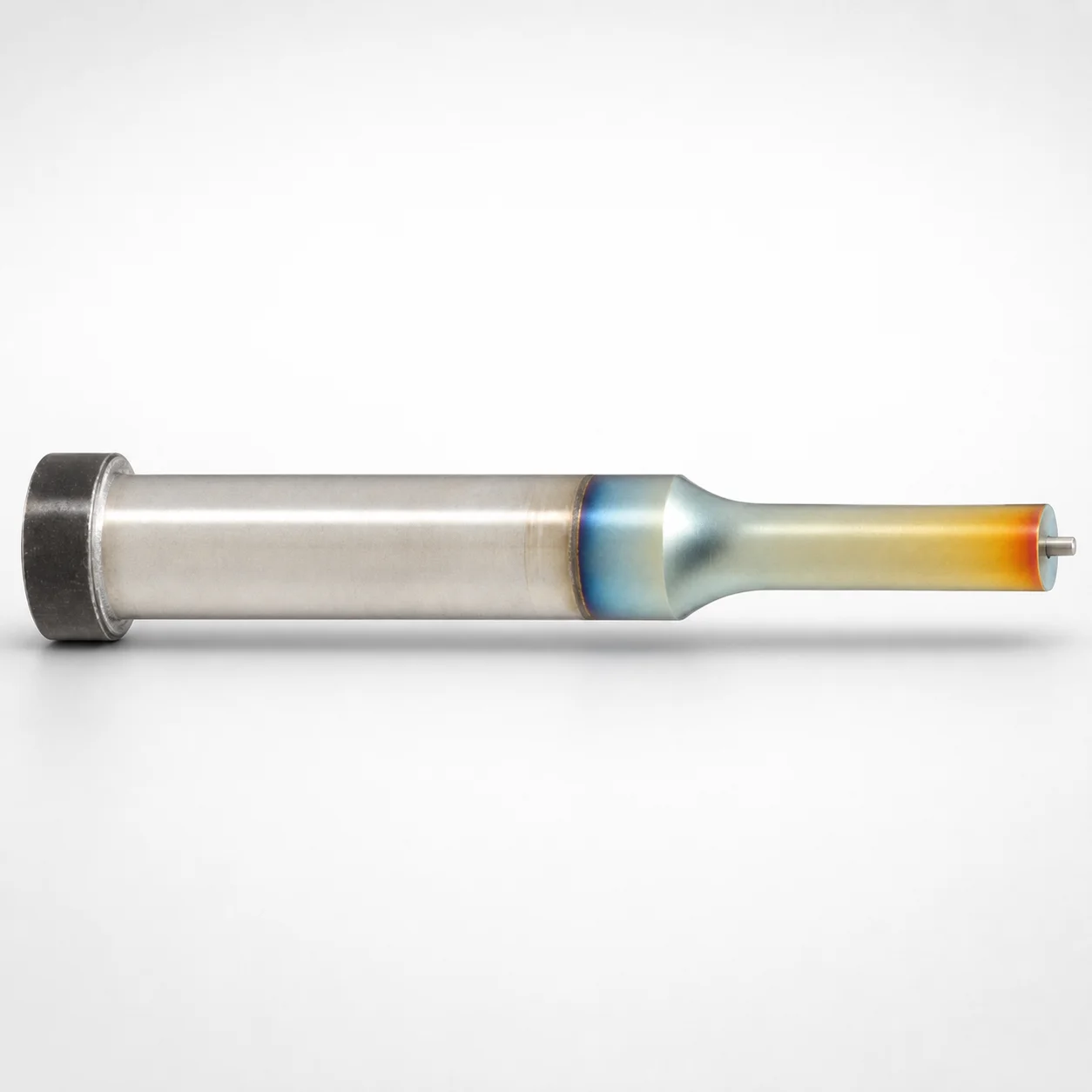
Jector Punches DLC + WPC Single-Stepped
Jector Punches (SKH40 steel) with DLC + WPC surface treatment deliver stable wear resistance for high-cycle die and mold assemblies, using a single-stepped shank to support consistent positioning during operation.
- Single-stepped shank design for dependable punch guidance
- DLC + WPC coating system for improved sliding and anti-wear performance
- Controlled head thickness reference T = 5 mm helps match plate thickness requirements
- Suitable for ejector systems in die sets using jector punch assemblies
Specifications
16625 configurations available
| Jector | Tip shape | Shank diameter D tolerance | B (Tip length) | D (Shank diameter) (mm) | L (L dimension) (mm) | LC (Full length alteration) (mm) | LCT (Head thickness tolerance change + total length alteration) (mm) | LMT(Head thickness tolerance change+Full length change) (mm) | Dimension P | PC (Tip dimension alteration) (mm) | Dimension R | Dimension W | WC (Tip dimension alteration) (mm) | type |
|---|---|---|---|---|---|---|---|---|---|---|---|---|---|---|
| Standard | Round | +0.005/0 | L | 4 | 50 ~ 80 | - | - | - | 1 ~ 3.99 | - | - | - | - | - |
| Standard | Round | +0.005/0 | L | 4 | - | 39 ~ 79.9 | - | - | 1 ~ 3.99 | - | - | - | - | - |
| Standard | Round | +0.005/0 | L | 4 | - | - | 39 ~ 79.9 | - | 1 ~ 3.99 | - | - | - | - | - |
| Standard | Round | +0.005/0 | L | 4 | - | - | - | 39 ~ 79.9 | 1 ~ 3.99 | - | - | - | - | - |
| Standard | Round | +0.005/0 | L | 5 | 50 ~ 80 | - | - | - | 2 ~ 4.99 | - | - | - | - | - |
| Standard | Round | +0.005/0 | L | 5 | 50 ~ 80 | - | - | - | - | 1.8 ~ 1.99 | - | - | - | - |
| Standard | Round | +0.005/0 | L | 5 | - | 39 ~ 79.9 | - | - | 2 ~ 4.99 | - | - | - | - | - |
| Standard | Round | +0.005/0 | L | 5 | - | 39 ~ 79.9 | - | - | - | 1.8 ~ 1.99 | - | - | - | - |
| Standard | Round | +0.005/0 | L | 5 | - | - | 39 ~ 79.9 | - | 2 ~ 4.99 | - | - | - | - | - |
| Standard | Round | +0.005/0 | L | 5 | - | - | 39 ~ 79.9 | - | - | 1.8 ~ 1.99 | - | - | - | - |
| Standard | Round | +0.005/0 | L | 5 | - | - | - | 39 ~ 79.9 | 2 ~ 4.99 | - | - | - | - | - |
| Standard | Round | +0.005/0 | L | 5 | - | - | - | 39 ~ 79.9 | - | 1.8 ~ 1.99 | - | - | - | - |
| Standard | Round | +0.005/0 | L | 6 | 50 ~ 80 | - | - | - | 2 ~ 5.99 | - | - | - | - | - |
| Standard | Round | +0.005/0 | L | 6 | 50 ~ 80 | - | - | - | - | 1.8 ~ 1.99 | - | - | - | - |
| Standard | Round | +0.005/0 | L | 6 | - | 39 ~ 79.9 | - | - | 2 ~ 5.99 | - | - | - | - | - |
| Standard | Round | +0.005/0 | L | 6 | - | 39 ~ 79.9 | - | - | - | 1.8 ~ 1.99 | - | - | - | - |
| Standard | Round | +0.005/0 | L | 6 | - | - | 39 ~ 79.9 | - | 2 ~ 5.99 | - | - | - | - | - |
| Standard | Round | +0.005/0 | L | 6 | - | - | 39 ~ 79.9 | - | - | 1.8 ~ 1.99 | - | - | - | - |
| Standard | Round | +0.005/0 | L | 6 | - | - | - | 39 ~ 79.9 | 2 ~ 5.99 | - | - | - | - | - |
| Standard | Round | +0.005/0 | L | 6 | - | - | - | 39 ~ 79.9 | - | 1.8 ~ 1.99 | - | - | - | - |
| Standard | Round | +0.005/0 | L | 8 | 50 ~ 100 | - | - | - | 3 ~ 7.99 | - | - | - | - | - |
| Standard | Round | +0.005/0 | L | 8 | 50 ~ 100 | - | - | - | - | 2.5 ~ 2.99 | - | - | - | - |
| Standard | Round | +0.005/0 | L | 8 | - | 33 ~ 99.9 | - | - | 3 ~ 7.99 | - | - | - | - | - |
| Standard | Round | +0.005/0 | L | 8 | - | 33 ~ 99.9 | - | - | - | 2.5 ~ 2.99 | - | - | - | - |
| Standard | Round | +0.005/0 | L | 8 | - | - | 33 ~ 99.9 | - | 3 ~ 7.99 | - | - | - | - | - |
| Standard | Round | +0.005/0 | L | 8 | - | - | 33 ~ 99.9 | - | - | 2.5 ~ 2.99 | - | - | - | - |
| Standard | Round | +0.005/0 | L | 8 | - | - | - | 33 ~ 99.9 | 3 ~ 7.99 | - | - | - | - | - |
| Standard | Round | +0.005/0 | L | 8 | - | - | - | 33 ~ 99.9 | - | 2.5 ~ 2.99 | - | - | - | - |
| Standard | Round | +0.005/0 | L | 10 | 50 ~ 100 | - | - | - | 3 ~ 9.99 | - | - | - | - | - |
| Standard | Round | +0.005/0 | L | 10 | 50 ~ 100 | - | - | - | - | 2.8 ~ 2.99 | - | - | - | - |
| Standard | Round | +0.005/0 | L | 10 | - | 33 ~ 99.9 | - | - | 3 ~ 9.99 | - | - | - | - | - |
| Standard | Round | +0.005/0 | L | 10 | - | 33 ~ 99.9 | - | - | - | 2.8 ~ 2.99 | - | - | - | - |
| Standard | Round | +0.005/0 | L | 10 | - | - | 33 ~ 99.9 | - | 3 ~ 9.99 | - | - | - | - | - |
| Standard | Round | +0.005/0 | L | 10 | - | - | 33 ~ 99.9 | - | - | 2.8 ~ 2.99 | - | - | - | - |
| Standard | Round | +0.005/0 | L | 10 | - | - | - | 33 ~ 99.9 | 3 ~ 9.99 | - | - | - | - | - |
| Standard | Round | +0.005/0 | L | 10 | - | - | - | 33 ~ 99.9 | - | 2.8 ~ 2.99 | - | - | - | - |
| Standard | Round | +0.005/0 | L | 13 | 50 ~ 100 | - | - | - | 6 ~ 12.99 | - | - | - | - | - |
| Standard | Round | +0.005/0 | L | 13 | 50 ~ 100 | - | - | - | - | 5 ~ 5.99 | - | - | - | - |
| Standard | Round | +0.005/0 | L | 13 | - | 33 ~ 99.9 | - | - | 6 ~ 12.99 | - | - | - | - | - |
| Standard | Round | +0.005/0 | L | 13 | - | 33 ~ 99.9 | - | - | - | 5 ~ 5.99 | - | - | - | - |
| Standard | Round | +0.005/0 | L | 13 | - | - | 33 ~ 99.9 | - | 6 ~ 12.99 | - | - | - | - | - |
| Standard | Round | +0.005/0 | L | 13 | - | - | 33 ~ 99.9 | - | - | 5 ~ 5.99 | - | - | - | - |
| Standard | Round | +0.005/0 | L | 13 | - | - | - | 33 ~ 99.9 | 6 ~ 12.99 | - | - | - | - | - |
| Standard | Round | +0.005/0 | L | 13 | - | - | - | 33 ~ 99.9 | - | 5 ~ 5.99 | - | - | - | - |
| Standard | Round | +0.005/0 | L | 16 | 60 ~ 100 | - | - | - | 10 ~ 15.99 | - | - | - | - | - |
| Standard | Round | +0.005/0 | L | 16 | 60 ~ 100 | - | - | - | - | 8 ~ 9.99 | - | - | - | - |
| Standard | Round | +0.005/0 | L | 16 | - | 37 ~ 99.9 | - | - | 10 ~ 15.99 | - | - | - | - | - |
| Standard | Round | +0.005/0 | L | 16 | - | 37 ~ 99.9 | - | - | - | 8 ~ 9.99 | - | - | - | - |
| Standard | Round | +0.005/0 | L | 16 | - | - | 37 ~ 99.9 | - | 10 ~ 15.99 | - | - | - | - | - |
| Standard | Round | +0.005/0 | L | 16 | - | - | 37 ~ 99.9 | - | - | 8 ~ 9.99 | - | - | - | - |
Product Guide
Application Scenarios+
These single-stepped jector punches are used in precision die and mold tooling where repeatable punch guidance and stable wear under sliding contact are critical. The DLC + WPC surface system on SKH40 supports high-cycle operation by improving anti-wear and reducing friction, helping maintain consistent die performance over time.
Common scenarios include automotive and industrial blanking/forming die sets, where the punch must stay accurately aligned in an ejector or jector assembly during frequent cycles. The single-stepped shank helps provide dependable positioning, supporting reliable seating against the die set and maintaining functional alignment.
They are also suitable for small precision parts production in compact die layouts, especially when controlled head thickness (reference T = 5 mm) must match plate/interface requirements. In addition, the availability of multiple tip shapes (round, rectangle, oblong, and double-flatted variants) allows matching to the die cut geometry for consistent forming contact.
Material & Process Details+
Constructed from SKH40 steel, this product is selected for wear-resistant performance in punch applications with sliding contact. The DLC + WPC surface treatment further enhances abrasion resistance and helps reduce galling during high-cycle use.
For mold and die engineers, the key trade-off is balancing wear resistance with impact toughness: the SKH40 base provides hardness for edge/punch stability, while the coated surface improves running performance. Because the exact quenched-and-tempered hardness level is not specified in the provided data, hardness (HRC) should be confirmed from the manufacturer’s heat-treatment record for the production lot.
- DLC + WPC: improved sliding/anti-wear performance for frequent cycling
- SKH40 base: wear-oriented tool steel for punch durability
- Note on variability: hardness and coating thickness can affect performance consistency—verify against your tool life targets
Sizing & Selection Guide+
Select jector punches by matching both the tip geometry and the shank/head/interface dimensions to the die set and guidance features. The shank diameter D ranges from 4 to 25 mm and is critical for fit in the mating guide/bushing bore—use the provided tolerance +0.005/0 with m5 as applicable for the shank diameter.
Choose the tip length/related dimension from the listed L ranges (e.g., 40–80, 40–100, 50–80, 50–100, 60–100) and confirm the full-length alteration parameter LC (about 32 to 90.1 mm) for your assembly stack-up. For interface matching, review the head thickness tolerance change parameters LCT and LMT (both provided as 32 to 90.1 mm ranges), ensuring the controlled head thickness reference T = 5 mm aligns with the plate requirement.
- Tip shape: round, rectangle, oblong, double-flatted round, radius rectangle—match die cut contact area
- Dimensional fit: verify mating bore tolerance and alignment to maintain seating reliability
Frequently Asked Questions
Which tip shapes are available for the Jector Punches DLC + WPC single-stepped series, and how do they affect die contact geometry?+
What shank diameter range and tolerance should I use to ensure correct seating in my die’s guide?+
How do the listed L ranges (L dimension) and LC/LCT/LMT ranges affect overall stack-up and total length verification?+
What performance advantage does the DLC + WPC coating provide versus using uncoated punches in high-cycle die work?+
Is T = 5 mm a fixed head thickness, and how should I incorporate tolerance changes when matching plates?+
Related Products






Need Custom Specifications?
Our engineering team can help with custom configurations, material selection, and volume pricing.