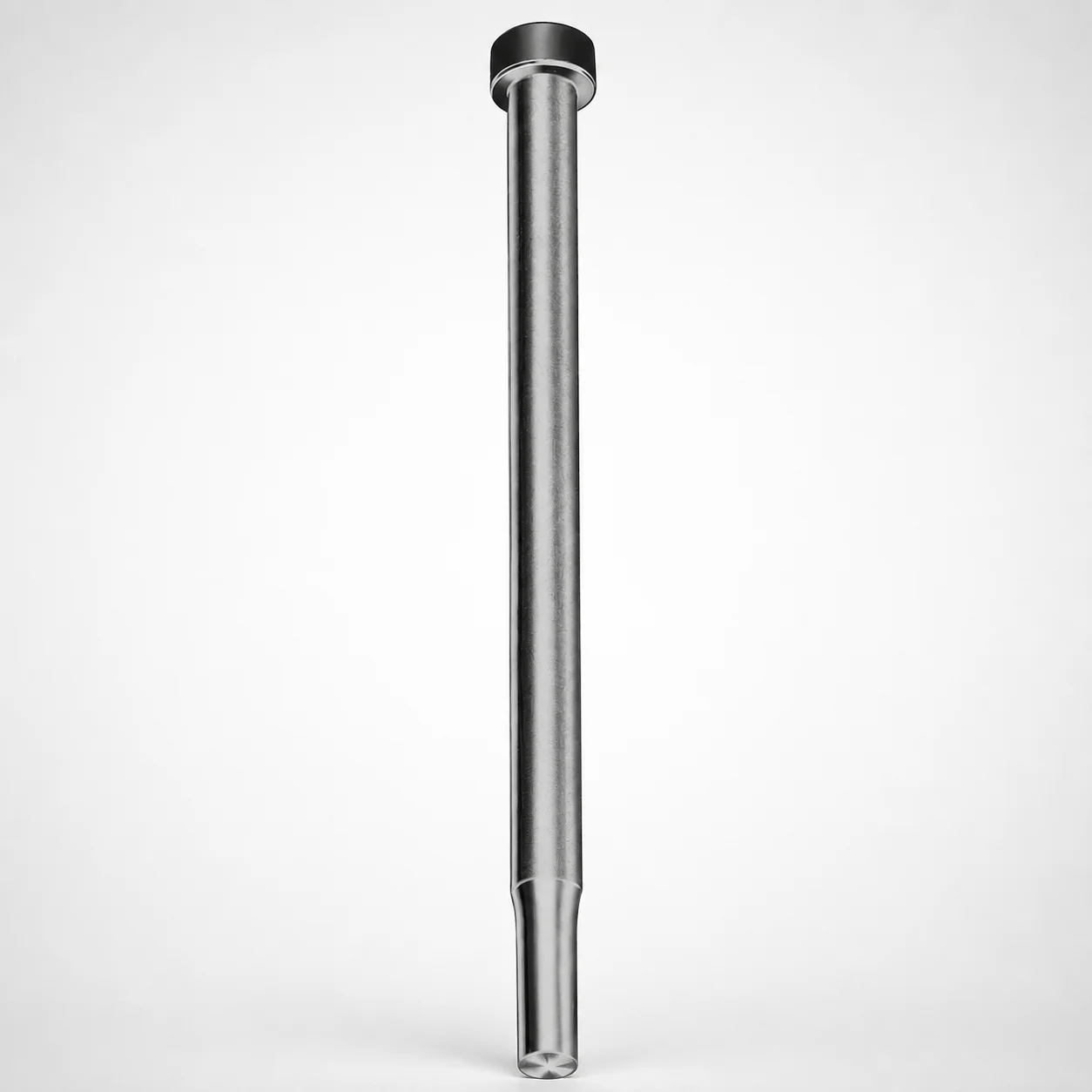
Close Space Punches Metric XNT DayTiN® Coating
Close Space Punches Metric with XNT DayTiN® coating from DAYTON are designed for compact die space where controlled punching performance is required. The coated surface helps resist wear and supports stable forming over repeated cycles.
- Compact close-space punch geometry for reliable part ejection and pressing clearance
- XNT DayTiN® coating improves surface durability under high-friction tooling conditions
- P dimension 0.8 mm fixed design supports consistent assembly compatibility
- Standardized tool part number format for efficient procurement and fast matching
Specifications
12 configurations available
| D (Shank dia.) (mm) | L (Length) (mm) | P Dimension (mm) |
|---|---|---|
| 02 | 40 ~ 100 | 0.8 |
| 02 | 40 ~ 100 | 0.81 ~ 2 |
| 03 | 40 ~ 100 | 1.1 ~ 2 |
| 03 | 40 ~ 100 | 2.01 ~ 3 |
| 04 | 40 ~ 100 | 1.3 ~ 3 |
| 04 | 40 ~ 100 | 3.01 ~ 4 |
| 05 | 40 ~ 100 | 1.3 ~ 4 |
| 05 | 40 ~ 100 | 4.01 ~ 5 |
| 06 | 40 ~ 100 | 1.3 ~ 5 |
| 06 | 40 ~ 100 | 5.01 ~ 6 |
| 07 | 40 ~ 100 | 1.3 ~ 6 |
| 07 | 40 ~ 100 | 6.01 ~ 7 |
Product Guide
Application Scenarios+
Close space punches are used inside injection and die tooling stations where the available “die space” is limited but punching performance must remain consistent. This metric punch format is well-suited for compact forming and piercing operations in automotive components, such as small bracket or connector housing inserts, where controlled pressing clearance and stable ejection reduce cycle-to-cycle variation.
The XNT DayTiN® coated working surface supports wear resistance during repeated high-friction contacts, making it a practical choice for electronics and appliance enclosure punch tooling that typically runs at higher duty cycles and requires smooth pressing to minimize surface damage.
- Compact die space layouts: close-space geometry helps fit between tight tooling features.
- Repeated punching cycles: the coating is intended to maintain durability for long runs.
- Metric tool builds: standardized part formats support faster matching to existing punch assemblies.
Material & Process Details+
The provided specification data focuses on the punch geometry and XNT DayTiN® coating rather than a specific base steel grade or heat-treatment target. Therefore, the material properties below emphasize what can be verified from the supplied information: the surface durability role of the coating in resisting wear under high-friction tooling conditions.
In tooling practice, DayTiN-type coating systems are selected to improve tribological performance—typically enhancing wear resistance at the punch’s working interface—while the toughness and core strength are governed by the underlying steel and its heat treatment. If you require hardness (HRC), specific steel equivalency (e.g., H13 / SKD61, M2 / SKH51), or nitriding/quench-and-temper details, please provide the base material certificate for this series so we can align the thermal profile to your expected loads.
- Coating function: reduced wear and more stable pressing over repeated cycles.
- Trade-off note: higher wear resistance coatings can still rely on a properly tempered core for impact toughness.
Sizing & Selection Guide+
To select the correct punch size, start with the shank diameter D and the close-space clearance requirement. Your options for D (Shank dia.) are fixed choices: 02, 03, 04, 05, 06, 07 (mm). Choose the smallest D that still ensures proper guidance and adequate strength for your tool layout.
Next, match the overall L (Length) to your tool stack-up. The fixed length range is 40 ~ 100 mm, so select L to reach the working end without bottoming in the guide or overextending through the holder.
Finally, confirm the P dimension because it defines the close-space punch relationship to adjacent components. Available P spans 0.8 ~ 6.01 mm (variable). Use P to align punching depth/clearance against the core or die cavity geometry; if your build requires repeatable pressing clearance, verify fit against the mating holder recess and allow for any assembly tolerances specified by your tool design.
- Fixed dimensions: L is fixed per selected length within 40–100 mm; D is discrete (02–07).
- Configurable dimension: P varies from 0.8 to 6.01 mm based on functional clearance needs.
Frequently Asked Questions
How do I choose the correct shank diameter (D) for a close-space punch build?+
The shank diameter D is available in discrete metric sizes: 02, 03, 04, 05, 06, 07 mm. Select the smallest D that still provides sufficient guidance and strength for your punch holder and the expected punching load.
If your holder bushings or guide rails are fixed, match D to the mating bore/bushing ID to maintain alignment across cycles.
What length (L) range is available and how should it be matched to the tool stack-up?+
This series specifies L (Length) = 40 ~ 100 mm. Choose L based on the distance from the punch seating interface to the working end, ensuring you avoid both insufficient reach and bottoming in the guide or holder.
For multi-plate assemblies, measure your stack height and select the closest available L that maintains safe clearance.
What is the functional role of the P dimension (0.8 ~ 6.01 mm) in close-space punching clearance?+
The P dimension is specified as 0.8 ~ 6.01 mm and is used to define the close-space relationship between the punch and adjacent tooling features.
In practice, match P to your die/cavity geometry to achieve the intended pressing clearance or effective punching depth while keeping the mechanism within available die space.
Does the XNT DayTiN® coating affect wear during repeated high-friction tool cycles?+
Yes. The coating is specified to improve surface durability under high-friction tooling conditions and to support stable forming over repeated cycles.
When selecting for long-run operations, prioritize this series where wear at the working interface is a limiting factor.
What tolerance considerations should I account for when matching this punch to mating assemblies?+
The available dimensions provided are the discrete D values (02–07 mm), fixed L within 40–100 mm, and variable P within 0.8 ~ 6.01 mm. Exact tolerance values are not included in the supplied data, so you should confirm tolerance requirements with your holder/punch assembly specification.
For repeatable clearance, verify the mating recess/guide fit and account for assembly-induced variation in your tool drawings.
Related Products






Need Custom Specifications?
Our engineering team can help with custom configurations, material selection, and volume pricing.