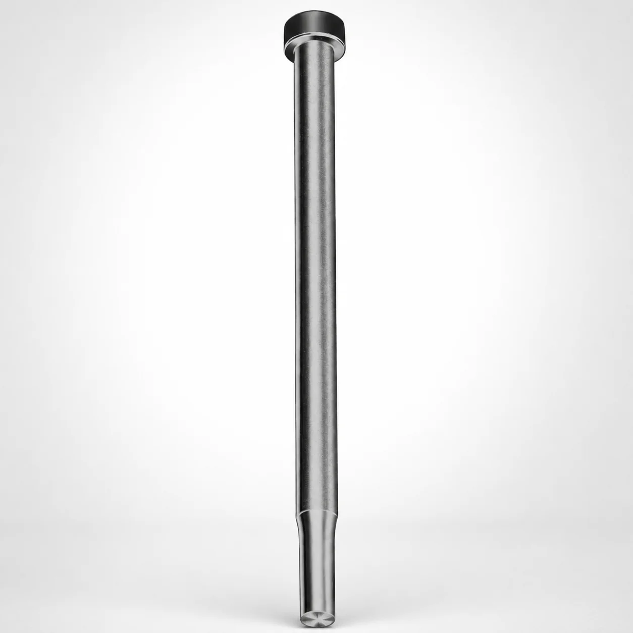
Close Space Punches Metric XNA Coating
Close Space Punches Metric (XNA coating) are precision punch components designed to support tight clearance punching and reliable workpiece forming in die assemblies. They help reduce tooling wear and maintain consistent punch performance over repeated cycles.
- Optimized for close-space punching applications in progressive and die stations
- XNA coating improves surface durability for long service life
- P dimension 0.8 mm supports controlled punch geometry at the working interface
- Metric shank diameters D 0.2–0.7 mm for flexible design matching to your tooling
Specifications
12 configurations available
| D (Shank dia.) (mm) | L (Length) (mm) | P Dimension (mm) |
|---|---|---|
| 02 | 40 ~ 100 | 0.8 |
| 02 | 40 ~ 100 | 0.81 ~ 2 |
| 03 | 40 ~ 100 | 1.1 ~ 2 |
| 03 | 40 ~ 100 | 2.01 ~ 3 |
| 04 | 40 ~ 100 | 1.3 ~ 3 |
| 04 | 40 ~ 100 | 3.01 ~ 4 |
| 05 | 40 ~ 100 | 1.3 ~ 4 |
| 05 | 40 ~ 100 | 4.01 ~ 5 |
| 06 | 40 ~ 100 | 1.3 ~ 5 |
| 06 | 40 ~ 100 | 5.01 ~ 6 |
| 07 | 40 ~ 100 | 1.3 ~ 6 |
| 07 | 40 ~ 100 | 6.01 ~ 7 |
Product Guide
Application Scenarios+
Close-space punches are used in injection and die tooling where a tight clearance between punch and die opening is essential to control material flow and maintain part geometry. In progressive stamping and multi-station forming layouts, these punches help achieve stable forming at high cycle counts by keeping punch tip engagement consistent throughout repeated strokes.
- Automotive connector and bracket tooling: suited for fine features where close clearance reduces burr formation and improves edge consistency; the XNA-coated surface supports long-run wear stability.
- Appliance and electronics enclosure components: used in die cavities requiring accurate workpiece alignment at the punch interface; the variant supports tight punching requirements through its close-space geometry.
- Medical device housing subassemblies: helpful when repeated punching must maintain predictable punch performance to protect dimensional tolerances on formed features.
The XNA coating is particularly relevant for production environments because it enhances surface durability, reducing the risk of accelerated wear that can drift clearance and alignment over time.
Material & Process Details+
Material and heat-treatment details are not provided in the available product data. For this reason, selection should be confirmed against the applicable DAYTON punch material specification before final tooling release.
- Coating state: the product variant includes an XNA coating, intended to improve surface durability and wear resistance at the working interface during repeated close-space punching.
- Hardness / wear-toughness trade-off: close-space punch life typically depends on the balance between high surface hardness (for wear resistance) and sufficient core toughness (to reduce chipping under impact loads). Since hardness (HRC) is not specified here, validate with the lot certificate or internal standard.
If multiple materials are available in your system, compare them based on expected contact stress, cutting/impact conditions, and whether your process prioritizes edge longevity or resistance to fracture.
Sizing & Selection Guide+
Select dimensions by matching the punch working interface geometry to the die cavity/core clearance requirements in your station. This series defines D as the metric shank diameter with available values 0.2–0.7 mm (listed as 02, 03, 04, 05, 06, 07) and L as the fixed length range 40–100 mm.
- Step 1 – Choose D (shank dia.): pick the shank diameter that fits your guide, holder, and alignment scheme without excessive play; the available options are discrete (02–07 corresponding to 0.2–0.7 mm).
- Step 2 – Choose L (length): select within 40–100 mm to ensure full engagement through the die stack while maintaining safe overhang and support.
- Step 3 – Verify P dimension: the P dimension spans 0.8–6.01 mm, which directly affects punch geometry at the working interface; confirm it against your die opening profile and required close clearance.
Tolerance and fit: this page provides dimension ranges but not tolerance limits; align with your tooling drawing standards and confirm allowable clearance between punch and guide components before machining the receiver.
Frequently Asked Questions
How do I choose the correct P dimension (0.8–6.01 mm) for close-space punching in a die station?+
The P dimension is the working-interface geometry parameter for this close-space punch series and ranges from 0.8 to 6.01 mm. Select the value that matches your die opening profile and the intended close clearance behavior in your station design.
Because the available data does not provide tolerance limits, verify the selected P against your tooling drawings and confirm it with your clearance/edge condition requirements.
What are the available shank diameters (D) for this series, and how do they affect alignment and guide fit?+
The shank diameter D is provided as metric discrete options: 02, 03, 04, 05, 06, 07, corresponding to 0.2–0.7 mm.
Choose D based on the holder/guide bore and the alignment scheme in your die assembly to minimize lateral play that could change close-space engagement during cycling.
Which length L options (40–100 mm) should I select for my die stack height?+
Length L is fixed as a configurable option within the range of 40–100 mm. Select L so the punch provides adequate stroke engagement through the die stack while preventing insufficient support or excessive overhang.
Confirm compatibility with your ejector/punch holder thickness and any stack-up features in the station.
Does the XNA coating reduce wear enough for long production runs in tight-clearance tooling?+
This variant specifies an XNA coating, which is intended to improve surface durability at the working interface for reliable performance under repeated punching.
While the provided data does not include hardness (HRC) or wear-test metrics, the coating is selected specifically to support longer service life and stable operation as clearance-critical wear progresses.
Can I use this close-space punch in progressive and multi-station die assemblies with tight tolerances?+
The series is described as optimized for close-space punching in progressive and die stations. That makes it appropriate for assemblies where repeated alignment at the punch interface is critical.
Use the specified D (0.2–0.7 mm), P (0.8–6.01 mm), and L (40–100 mm) to match your cavity/core clearance design, and confirm tolerances against your tooling standards.
Related Products






Need Custom Specifications?
Our engineering team can help with custom configurations, material selection, and volume pricing.