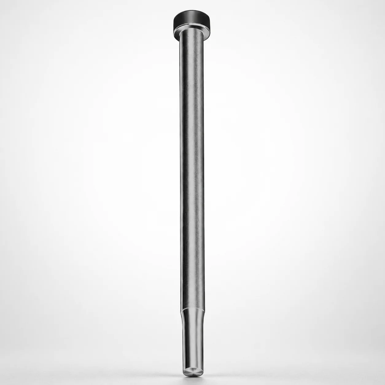
Close Space Punches - Metric CRN Coating
Close Space Punches - Metric CRN Coating are designed for reliable punching in tight die cavities, where close clearance and repeatability matter most. The DAYTON tool steel construction with CRN coating supports consistent cycle performance.
- Optimized for close-clearance punching applications in compact tooling
- CRN coating helps reduce wear and improves tool life under production loads
- Metric shank options support proper fit to standard die layouts
- Suitable for progressive dies and precision forming operations requiring stable results
Specifications
12 configurations available
| D (Shank dia.) (mm) | L (Length) (mm) | P Dimension (mm) |
|---|---|---|
| 02 | 40 ~ 100 | 0.8 |
| 02 | 40 ~ 100 | 0.81 ~ 2 |
| 03 | 40 ~ 100 | 1.1 ~ 2 |
| 03 | 40 ~ 100 | 2.01 ~ 3 |
| 04 | 40 ~ 100 | 1.3 ~ 3 |
| 04 | 40 ~ 100 | 3.01 ~ 4 |
| 05 | 40 ~ 100 | 1.3 ~ 4 |
| 05 | 40 ~ 100 | 4.01 ~ 5 |
| 06 | 40 ~ 100 | 1.3 ~ 5 |
| 06 | 40 ~ 100 | 5.01 ~ 6 |
| 07 | 40 ~ 100 | 1.3 ~ 6 |
| 07 | 40 ~ 100 | 6.01 ~ 7 |
Product Guide
Application Scenarios+
Close clearance forming depends on punch geometry that stays stable under repeated impact, especially inside compact die cavities. These metric close space punches are commonly used in progressive dies for small automotive and appliance components, where the punch must maintain repeatable positioning while working with tight clearance between punch and die.
The CRN coating variant is suited for production runs that experience adhesive/abrasive wear, helping maintain consistent cutting edges through higher cycles. A second use case is precision metal stamping for connectors and thin sheet hardware, where close tolerances and stable force balance reduce dimensional drift across long batches.
They are also effective in precision forming operations that require predictable penetration with a defined shank size for compatibility with standard die layouts. Select the appropriate metric shank diameter (D: 2–7 mm) and a length within L (40–100 mm) to match the available die block stack-up and guide engagement.
Material & Process Details+
These punches are manufactured from DAYTON tool steel and provided with a CRN (chromium nitride) coating to improve surface performance during punching. While the exact steel grade and heat-treatment state are not specified in the provided data, the intended metallurgy is for wear-resistant cutting service where impact loads and sliding contact occur.
- CRN coating: increases surface hardness and reduces wear mechanisms such as adhesive transfer and abrasion, improving tool life.
- Tool steel substrate: supports toughness needed for punching under production cycling; this provides a balance between edge strength and wear durability.
When comparing coated tooling options, a CRN-coated approach is typically chosen to extend life in high-cycle close-clearance operations where wear dominates over purely brute-force toughness.
Sizing & Selection Guide+
Select dimensions to ensure the punch fits the die set and provides the required working engagement in close-clearance tooling. This series uses a metric shank diameter D of 02, 03, 04, 05, 06, 07 mm, and a fixed length L in the range of 40 to 100 mm.
- Match D to the guide/punch holder bore and the standard die layout you are using; using the correct shank diameter is essential for alignment in progressive and close-clearance dies.
- Choose L to cover the full die stack-up and ensure sufficient guidance/engagement without bottoming in the holder.
- Set the P dimension between 0.8 and 6.01 mm according to the required close-clearance geometry and punch working profile.
For best repeatability, confirm your press and die set tolerances for close-clearance operation; even small deviations in D and P can affect clearance consistency and part quality. D and L are the fixed series-controlled sizing elements, while P is variable within the stated range.
Frequently Asked Questions
How do I choose the correct shank diameter (D) for close-clearance punching in a progressive die?+
What length range (L) should be selected to avoid under- or over-engagement in the die stack?+
What is the role of the CRN coating in reducing wear for production punching?+
How do I select the P dimension when designing for close clearance?+
Is this punch configuration suitable for precision forming beyond progressive stamping?+
Related Products






Need Custom Specifications?
Our engineering team can help with custom configurations, material selection, and volume pricing.