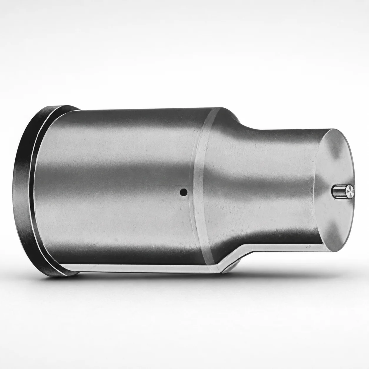
Metric Extended Range Ejector Punches XNAD Coating
Metric Extended Range Ejector Punches (XNAD Coating) are designed for close space tool layouts, delivering stable punch guidance and consistent ejection during production. The extended range geometry helps maintain effective contact where press-fit clearances are limited.
- Close space punch tip geometry supports dependable material piercing and ejecting in tight dies.
- XNAD coating improves surface durability to help resist wear under repeated cycles.
- Supports tight assembly by controlling point and shank proportions for stable alignment.
- Built for metric progressive and transfer tooling where ejector access is restricted.
Specifications
50 configurations available
| Tip shape | D (Shank dia.) (mm) | L1 (Point Length) (mm) | L (Length) (mm) | P Dimension (mm) | W Dimension (mm) | R Dimension (mm) |
|---|---|---|---|---|---|---|
| H | 40 | 25 ~ 30 | 63 ~ 100 | 20 ~ 39.95 | 8 ~ 39.95 | - |
| H | 45 | 25 ~ 30 | 63 ~ 100 | 25 ~ 44.95 | 9 ~ 44.95 | - |
| H | 50 | 25 ~ 30 | 63 ~ 100 | 30 ~ 49.95 | 10 ~ 49.95 | - |
| H | 56 | 25 ~ 30 | 63 ~ 100 | 35 ~ 55.95 | 11 ~ 55.95 | - |
| H | 63 | 25 ~ 30 | 63 ~ 100 | 40 ~ 62.95 | 12 ~ 62.95 | - |
| J | 40 | 25 ~ 30 | 63 ~ 100 | 20 ~ 39.95 | 8 ~ 39.95 | - |
| J | 45 | 25 ~ 30 | 63 ~ 100 | 25 ~ 44.95 | 9 ~ 44.95 | - |
| J | 50 | 25 ~ 30 | 63 ~ 100 | 30 ~ 49.95 | 10 ~ 49.95 | - |
| J | 56 | 25 ~ 30 | 63 ~ 100 | 35 ~ 55.95 | 11 ~ 55.95 | - |
| J | 63 | 25 ~ 30 | 63 ~ 100 | 40 ~ 62.95 | 12 ~ 62.95 | - |
| K | 40 | 25 ~ 30 | 63 ~ 100 | 20 ~ 39.95 | 8 ~ 39.95 | 0.2 ~ 19.975 |
| K | 45 | 25 ~ 30 | 63 ~ 100 | 25 ~ 44.95 | 9 ~ 44.95 | 0.2 ~ 22.475 |
| K | 50 | 25 ~ 30 | 63 ~ 100 | 30 ~ 49.95 | 10 ~ 49.95 | 0.2 ~ 24.975 |
| K | 56 | 25 ~ 30 | 63 ~ 100 | 35 ~ 55.95 | 11 ~ 55.95 | 0.2 ~ 27.975 |
| K | 63 | 25 ~ 30 | 63 ~ 100 | 40 ~ 62.95 | 12 ~ 62.95 | 0.2 ~ 31.475 |
| N | 40 | 25 ~ 30 | 63 ~ 100 | - | 8 ~ 39.95 | - |
| N | 45 | 25 ~ 30 | 63 ~ 100 | - | 9 ~ 44.95 | - |
| N | 50 | 25 ~ 30 | 63 ~ 100 | - | 10 ~ 49.95 | - |
| N | 56 | 25 ~ 30 | 63 ~ 100 | - | 11 ~ 55.95 | - |
| N | 63 | 25 ~ 30 | 63 ~ 100 | - | 12 ~ 62.95 | - |
| O | 40 | 25 ~ 30 | 63 ~ 100 | 20 ~ 39.95 | 8 ~ 39.95 | - |
| O | 45 | 25 ~ 30 | 63 ~ 100 | 25 ~ 44.95 | 9 ~ 44.95 | - |
| O | 50 | 25 ~ 30 | 63 ~ 100 | 30 ~ 49.95 | 10 ~ 49.95 | - |
| O | 56 | 25 ~ 30 | 63 ~ 100 | 35 ~ 55.95 | 11 ~ 55.95 | - |
| O | 63 | 25 ~ 30 | 63 ~ 100 | 40 ~ 62.95 | 12 ~ 62.95 | - |
| R | 40 | 25 ~ 30 | 63 ~ 100 | 20 ~ 39.95 | 8 ~ 39.95 | - |
| R | 45 | 25 ~ 30 | 63 ~ 100 | 25 ~ 44.95 | 9 ~ 44.95 | - |
| R | 50 | 25 ~ 30 | 63 ~ 100 | 30 ~ 49.95 | 10 ~ 49.95 | - |
| R | 56 | 25 ~ 30 | 63 ~ 100 | 35 ~ 55.95 | 11 ~ 55.95 | - |
| R | 63 | 25 ~ 30 | 63 ~ 100 | 40 ~ 62.95 | 12 ~ 62.95 | - |
| V | 40 | 25 ~ 30 | 63 ~ 100 | 20 ~ 39.95 | 8 ~ 39.95 | - |
| V | 45 | 25 ~ 30 | 63 ~ 100 | 25 ~ 44.95 | 9 ~ 44.95 | - |
| V | 50 | 25 ~ 30 | 63 ~ 100 | 30 ~ 49.95 | 10 ~ 49.95 | - |
| V | 56 | 25 ~ 30 | 63 ~ 100 | 35 ~ 55.95 | 11 ~ 55.95 | - |
| V | 63 | 25 ~ 30 | 63 ~ 100 | 40 ~ 62.95 | 12 ~ 62.95 | - |
| X | 40 | 25 ~ 30 | 63 ~ 100 | 20 ~ 39.95 | - | - |
| X | 45 | 25 ~ 30 | 63 ~ 100 | 25 ~ 44.95 | - | - |
| X | 50 | 25 ~ 30 | 63 ~ 100 | 30 ~ 49.95 | - | - |
| X | 56 | 25 ~ 30 | 63 ~ 100 | 35 ~ 55.95 | - | - |
| X | 63 | 25 ~ 30 | 63 ~ 100 | 40 ~ 62.95 | - | - |
| Y | 40 | 25 ~ 30 | 63 ~ 100 | 20 ~ 39.95 | 8 ~ 39.95 | 0.2 ~ 19.975 |
| Y | 45 | 25 ~ 30 | 63 ~ 100 | 25 ~ 44.95 | 9 ~ 44.95 | 0.2 ~ 22.475 |
| Y | 50 | 25 ~ 30 | 63 ~ 100 | 30 ~ 49.95 | 10 ~ 49.95 | 0.2 ~ 24.975 |
| Y | 56 | 25 ~ 30 | 63 ~ 100 | 35 ~ 55.95 | 11 ~ 55.95 | 0.2 ~ 27.975 |
| Y | 63 | 25 ~ 30 | 63 ~ 100 | 40 ~ 62.95 | 12 ~ 62.95 | 0.2 ~ 31.475 |
| Z | 40 | 25 ~ 30 | 63 ~ 100 | - | 8 ~ 39.95 | 0.2 ~ 19.975 |
| Z | 45 | 25 ~ 30 | 63 ~ 100 | - | 9 ~ 44.95 | 0.2 ~ 22.475 |
| Z | 50 | 25 ~ 30 | 63 ~ 100 | - | 10 ~ 49.95 | 0.2 ~ 24.975 |
| Z | 56 | 25 ~ 30 | 63 ~ 100 | - | 11 ~ 55.95 | 0.2 ~ 27.975 |
| Z | 63 | 25 ~ 30 | 63 ~ 100 | - | 12 ~ 62.95 | 0.2 ~ 31.475 |
Product Guide
Application Scenarios+
This metric extended-range punch set is used in injection and stamping die tooling where ejector access is restricted and space around the cavity is limited. The close-space tip geometry helps maintain stable piercing and ejection even when press-fit clearances reduce the available guidance length.
- Automotive interior connector and bracket molds: Works well in progressive or transfer tooling stations that require reliable part release under tight tool layouts, helping keep punch alignment through repeated cycles.
- Consumer electronics housings: The extended-range form supports ejection where the ejector must reach into deep or narrow features without interference from surrounding components.
- Medical device housing inserts: The durable surface finish (XNAD coating) improves wear resistance for consistent ejection performance over production runs with frequent cycling.
XNAD coating is especially suited for high-cycle environments because it enhances surface durability, reducing wear-driven changes to fit and guidance.
Material & Process Details+
The provided specifications describe a coated ejector punch geometry and dimensional family, but no specific steel grade (e.g., SKD61/H13, AISI M2) or hardness (HRC) is included in the input data. As a result, the exact material heat treatment state and hardness values cannot be stated from the current listing.
- Coating system: XNAD coating is specified, indicating an emphasis on surface wear resistance for repeated ejection cycles.
- Wear vs. toughness trade-off: For ejector punches, coatings typically improve resistance to scuffing and abrasive wear; base steel toughness remains critical to prevent chipping at the point during high impact ejection.
- Heat treatment: Select the base steel and heat treat (e.g., quenched & tempered or nitrided systems) that match your expected load and cycle rate; coordinate with your mold steel datasheet since it is not specified here.
If you confirm the preferred base steel grade for series 250301827784, we can map it to the expected HRC range and corresponding heat treatment route.
Sizing & Selection Guide+
Select the ejector punch by matching the shank diameter (D) and overall length (L) to the core/cavity layout and required stroke reach. For this series, D is available in 40, 45, 50, 56, 63 mm, while L is 63 to 100 mm.
- Point length (L1): fixed at 25 to 30 mm, which should align with the effective piercing/engagement depth in your ejection path.
- Space-constraint control: use the variable P (20–39.95, 25–44.95, 30–49.95, 35–55.95, 40–62.95 mm) and W (8–39.95, 9–44.95, 10–49.95, 11–55.95, 12–62.95 mm) to fit your die pocketing and guide clearance.
- Tip geometry radius (R): choose from 0.2–19.975 up to 0.2–31.475 mm depending on the selected close-space tip form for reliable release without excessive stress concentration.
Confirm your tooling tolerances and guide-fit requirements with your builder; because tolerances are not provided here, final fit should follow your standard punch-to-bushing clearance practice for progressive/transfer systems.
Frequently Asked Questions
Which dimensions should I verify first when selecting series 250301827784 extended-range ejector punches for a tight die layout?+
How does the close-space tip geometry affect ejection reliability in limited ejector access designs?+
What XNAD coating benefit should I expect for wear in high-cycle injection or transfer molding tooling?+
Can I choose different tip shapes (H, J, K, etc.) without changing the core dimensions of the punch?+
What guidance do you have on tolerance/fit for these ejector punches, given that no tolerance values are shown?+
Related Products






Need Custom Specifications?
Our engineering team can help with custom configurations, material selection, and volume pricing.