
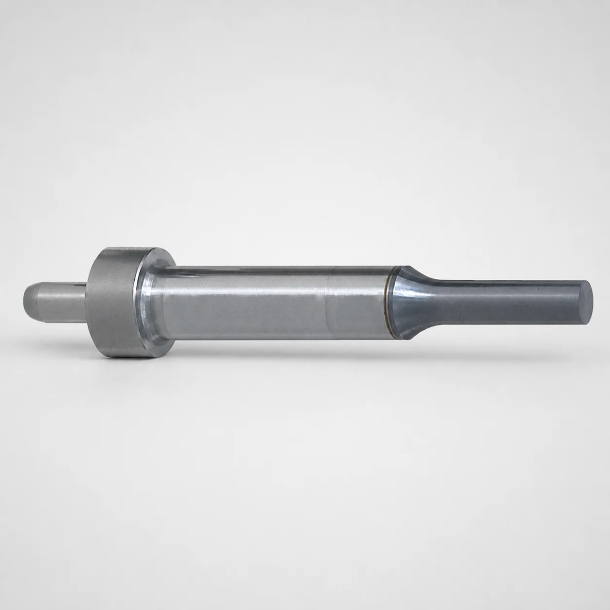
JIS Standard SKH51 Steel Ejector Punches for Heavy Load with Dowel Holes
Ejector punches for heavy load with dowel holes (SKH51 steel) are designed for rigid mold clamping systems where repeatable center alignment and controlled ejection are required. The dowel-hole mounting style supports stable punch guidance under heavy duty cycles.
- Single-stepped shank with locating dowel hole for consistent positioning
- SKH51 steel construction supports wear resistance for long service life
- Designed for tight shank diameter control with m5 tolerance reference
- Used in heavy-load tooling for locating and ejection in production molds
Specifications
200 configurations available
| Jector | Tip shape | B (Tip length) | D (Shank diameter) (mm) | P (Tip dimension) (mm) | L (L dimension) (mm) | LC (Full length alteration) (mm) | R (Tip corner R) (mm) | W (Tip dimension) (mm) | type |
|---|---|---|---|---|---|---|---|---|---|
| Standard type | Round | L | 10 | 5 ~ 9.99 | 60 ~ 130 | - | - | - | - |
| Standard type | Round | L | 10 | 5 ~ 9.99 | - | 53 ~ 129.9 | - | - | - |
| Standard type | Round | L | 13 | 6 ~ 12.99 | 60 ~ 130 | - | - | - | - |
| Standard type | Round | L | 13 | 6 ~ 12.99 | - | 53 ~ 129.9 | - | - | - |
| Standard type | Round | L | 16 | 10 ~ 15.99 | 70 ~ 130 | - | - | - | - |
| Standard type | Round | L | 16 | 10 ~ 15.99 | - | 53 ~ 129.9 | - | - | - |
| Standard type | Round | L | 20 | 13 ~ 19.99 | 70 ~ 130 | - | - | - | - |
| Standard type | Round | L | 20 | 13 ~ 19.99 | - | 47 ~ 129.9 | - | - | - |
| Standard type | Round | L | 25 | 18 ~ 24.99 | 70 ~ 130 | - | - | - | - |
| Standard type | Round | L | 25 | 18 ~ 24.99 | - | 53 ~ 129.9 | - | - | - |
| Standard type | Round | S | 10 | 5 ~ 9.99 | 60 ~ 130 | - | - | - | - |
| Standard type | Round | S | 10 | 5 ~ 9.99 | - | 54 ~ 129.9 | - | - | - |
| Standard type | Round | S | 13 | 6 ~ 12.99 | 60 ~ 130 | - | - | - | - |
| Standard type | Round | S | 13 | 6 ~ 12.99 | - | 54 ~ 129.9 | - | - | - |
| Standard type | Round | S | 16 | 10 ~ 15.99 | 60 ~ 130 | - | - | - | - |
| Standard type | Round | S | 16 | 10 ~ 15.99 | - | 54 ~ 129.9 | - | - | - |
| Standard type | Round | S | 20 | 13 ~ 19.99 | 60 ~ 130 | - | - | - | - |
| Standard type | Round | S | 20 | 13 ~ 19.99 | - | 54 ~ 129.9 | - | - | - |
| Standard type | Round | S | 25 | 18 ~ 24.99 | 60 ~ 130 | - | - | - | - |
| Standard type | Round | S | 25 | 18 ~ 24.99 | - | 54 ~ 129.9 | - | - | - |
| Standard type | Rectangle | L | 10 | 5 ~ 9.97 | 60 ~ 130 | - | - | 5 ~ 9.97 | - |
| Standard type | Rectangle | L | 10 | 5 ~ 9.97 | - | 53 ~ 129.9 | - | 5 ~ 9.97 | - |
| Standard type | Rectangle | L | 13 | 6 ~ 12.97 | 60 ~ 130 | - | - | 6 ~ 12.97 | - |
| Standard type | Rectangle | L | 13 | 6 ~ 12.97 | - | 53 ~ 129.9 | - | 6 ~ 12.97 | - |
| Standard type | Rectangle | L | 16 | 6 ~ 15.97 | 70 ~ 130 | - | - | 6 ~ 15.97 | - |
| Standard type | Rectangle | L | 16 | 6 ~ 15.97 | - | 53 ~ 129.9 | - | 6 ~ 15.97 | - |
| Standard type | Rectangle | L | 20 | 6 ~ 19.97 | 70 ~ 130 | - | - | 6 ~ 19.97 | - |
| Standard type | Rectangle | L | 20 | 6 ~ 19.97 | - | 53 ~ 129.9 | - | 6 ~ 19.97 | - |
| Standard type | Rectangle | L | 25 | 6 ~ 24.97 | 70 ~ 130 | - | - | 6 ~ 24.97 | - |
| Standard type | Rectangle | L | 25 | 6 ~ 24.97 | - | 53 ~ 129.9 | - | 6 ~ 24.97 | - |
| Standard type | Rectangle | S | 10 | 5 ~ 9.97 | 60 ~ 130 | - | - | 5 ~ 9.97 | - |
| Standard type | Rectangle | S | 10 | 5 ~ 9.97 | - | 54 ~ 129.9 | - | 5 ~ 9.97 | - |
| Standard type | Rectangle | S | 13 | 6 ~ 12.97 | 60 ~ 130 | - | - | 6 ~ 12.97 | - |
| Standard type | Rectangle | S | 13 | 6 ~ 12.97 | - | 54 ~ 129.9 | - | 6 ~ 12.97 | - |
| Standard type | Rectangle | S | 16 | 6 ~ 15.97 | 60 ~ 130 | - | - | 6 ~ 15.97 | - |
| Standard type | Rectangle | S | 16 | 6 ~ 15.97 | - | 54 ~ 129.9 | - | 6 ~ 15.97 | - |
| Standard type | Rectangle | S | 20 | 6 ~ 19.97 | 60 ~ 130 | - | - | 6 ~ 19.97 | - |
| Standard type | Rectangle | S | 20 | 6 ~ 19.97 | - | 54 ~ 129.9 | - | 6 ~ 19.97 | - |
| Standard type | Rectangle | S | 25 | 6 ~ 24.97 | 60 ~ 130 | - | - | 6 ~ 24.97 | - |
| Standard type | Rectangle | S | 25 | 6 ~ 24.97 | - | 54 ~ 129.9 | - | 6 ~ 24.97 | - |
| Standard type | Oblong | L | 10 | 5 ~ 9.97 | 60 ~ 130 | - | - | 5 ~ 9.97 | - |
| Standard type | Oblong | L | 10 | 5 ~ 9.97 | - | 53 ~ 129.9 | - | 5 ~ 9.97 | - |
| Standard type | Oblong | L | 13 | 6 ~ 12.97 | 60 ~ 130 | - | - | 6 ~ 12.97 | - |
| Standard type | Oblong | L | 13 | 6 ~ 12.97 | - | 53 ~ 129.9 | - | 6 ~ 12.97 | - |
| Standard type | Oblong | L | 16 | 6 ~ 15.97 | 70 ~ 130 | - | - | 6 ~ 15.97 | - |
| Standard type | Oblong | L | 16 | 6 ~ 15.97 | - | 53 ~ 129.9 | - | 6 ~ 15.97 | - |
| Standard type | Oblong | L | 20 | 6 ~ 19.97 | 70 ~ 130 | - | - | 6 ~ 19.97 | - |
| Standard type | Oblong | L | 20 | 6 ~ 19.97 | - | 53 ~ 129.9 | - | 6 ~ 19.97 | - |
| Standard type | Oblong | L | 25 | 6 ~ 24.97 | 70 ~ 130 | - | - | 6 ~ 24.97 | - |
| Standard type | Oblong | L | 25 | 6 ~ 24.97 | - | 47 ~ 129.9 | - | 6 ~ 24.97 | - |
Product Guide
Application Scenarios+
Ejector punches in heavy-load injection mold tooling use the dowel-hole mounting style to maintain repeatable center alignment during high-cycle ejection. This style is suited for rigid clamping systems where positional drift can cause wear, misalignment, or inconsistent part release.
- Automotive connector and sensor housing molds: The single-stepped shank with a locating dowel hole helps stabilize punch guidance under repeated short-cycle ejection loads, improving alignment between runner/ejector interfaces and core features.
- Industrial appliance housings and thick-wall components: The SKH51 steel construction supports wear resistance for long service life when ejector forces and sliding contacts are sustained.
- Precision multi-cavity tooling: Controlled shank diameter and the m5 tolerance reference support consistent fit into guide/locating features, reducing cumulative variation across cavities.
Material & Process Details+
The punches are manufactured from JIS Standard SKH51, a high-speed steel grade widely used in cutting and wear applications. In tooling terms, SKH51 is commonly selected for excellent wear resistance compared with lower-alloy ejector steels, helping maintain edge and sliding performance under heavy ejection cycles.
- Heat treatment state: Supplied SKH51 ejector punches are typically hardened and tempered for a balance of hardness and toughness suitable for mold ejector duty (exact HRC can vary by supplier process).
- Hardness & wear vs. toughness trade-off: High hardness improves abrasion resistance on the shank and tip surfaces, while tempering maintains adequate toughness to resist chipping during repeated shock loading.
- Compared to pre-hardened/cheaper steels: SKH51 generally offers better wear resistance, while the trade-off is that it can be less forgiving to impact than lower-hardness grades if sizing/fit induces excessive stress.
Sizing & Selection Guide+
Select the ejector punch dimensions by matching the tip geometry and shank requirements to the mold core/cavity and the ejector guide system. Start with the D (shank diameter) options 10, 13, 16, 20, 25 mm to align with your guide bushing or ejector retainer bore. For controlled guidance, the design reference uses m5 tolerance for the shank fit.
- Tip shape: Choose based on the mating ejector pocket feature—available options include Round, Rectangle, Oblong, Double flatted round, Radius rectangle.
- Tip size: Set P (tip dimension) from 5 ~ 18 mm and confirm corner radius R = 0.15 ~ 12.48 mm as required for your pocket geometry.
- Actuation length: Use L (e.g., ranges include 60–130, 70–130, 60–100, 70–100 mm) and verify LC (full length alteration) per your stack-up (ranges listed per configuration).
- Configurable vs fixed: Tip shape and tip dimensions are configurable via P/R/W selection, while D and the shank/tip interface are fixed once the dimension set is chosen.
Frequently Asked Questions
Which SKH51 ejector punch shank diameters (D) are available, and how do I choose the correct fit for m5 guide features?+
How do I match the ejector punch tip dimension (P), corner radius (R), and tip width (W) to the ejector pocket geometry?+
What length parameters should I verify—L and LC—when designing the ejector stroke and stack-up?+
Is the dowel-hole mounting style intended for alignment under heavy duty cycles, and what changes if I use a spring/pin reinforced type?+
Which tip shape should I choose for thick-wall parts where ejector contact area and load distribution matter?+
Related Products

Metric Dowel Punches for Heavy Load with Single-Stepped Shank (M5)

Metric Center Dowel Punches for Heavy Load TiCN Coated

SKH51 Steel TiCN Coating Ejector Punches for Heavy Load with Dowel Holes

RW Coated Dowel Punches for Heavy Load - Single-Stepped Shank

Center Dowel Ejector Punches for Heavy Load (RW Coating) - SKH51 Steel
Center Dowel Punches for Heavy Load (HW Coating) | Metric
Need Custom Specifications?
Our engineering team can help with custom configurations, material selection, and volume pricing.