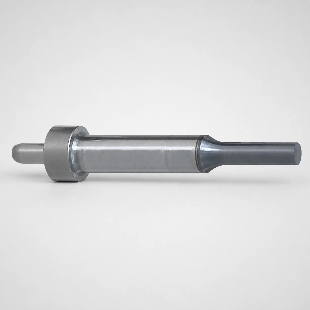
Center Dowel Punches for Heavy Load (HW Coating) | Metric
Center Dowel Punches for Heavy Load (HW coating) deliver reliable alignment during die work by combining a locating dowel hole with a single-stepped shank design. Built for consistent performance in production environments.
- Single-stepped shank with a locating dowel hole for repeatable positioning and center control
- Durable HW coating supports abrasion resistance in heavy-duty punching
- Ground shank diameter profile with m5 tolerance for stable fits in guide components
- Metric style heavy-load center punching for applications in progressive and transfer dies
Specifications
720 configurations available
| Tip shape | Material | B (Tip length) | D (Shank diameter) (mm) | P (Tip dimension) (mm) | L (L dimension) (mm) | LC (Full length alteration) (mm) | PC (Tip dimension alteration) (mm) | R (Tip corner R) (mm) | W (Tip dimension) (mm) | WC (Tip dimension alteration) (mm) | type |
|---|---|---|---|---|---|---|---|---|---|---|---|
| Round | SKH51 Equivalent (M2) | L | 10 | 3 ~ 9.99 | 60 ~ 150 | - | - | - | - | - | - |
| Round | SKH51 Equivalent (M2) | L | 10 | - | 60 ~ 150 | - | 1.5 ~ 2.99 | - | - | - | - |
| Round | SKH51 Equivalent (M2) | L | 10 | 3 ~ 9.99 | - | 37 ~ 149.9 | - | - | - | - | - |
| Round | SKH51 Equivalent (M2) | L | 10 | - | - | 37 ~ 149.9 | 1.5 ~ 2.99 | - | - | - | - |
| Round | SKH51 Equivalent (M2) | L | 13 | 6 ~ 12.99 | 60 ~ 150 | - | - | - | - | - | - |
| Round | SKH51 Equivalent (M2) | L | 13 | - | 60 ~ 150 | - | 3 ~ 5.99 | - | - | - | - |
| Round | SKH51 Equivalent (M2) | L | 13 | 6 ~ 12.99 | - | 37 ~ 149.9 | - | - | - | - | - |
| Round | SKH51 Equivalent (M2) | L | 13 | - | - | 37 ~ 149.9 | 3 ~ 5.99 | - | - | - | - |
| Round | SKH51 Equivalent (M2) | L | 16 | 10 ~ 15.99 | 70 ~ 150 | - | - | - | - | - | - |
| Round | SKH51 Equivalent (M2) | L | 16 | - | 70 ~ 150 | - | 5 ~ 9.99 | - | - | - | - |
| Round | SKH51 Equivalent (M2) | L | 16 | 10 ~ 15.99 | - | 37 ~ 149.9 | - | - | - | - | - |
| Round | SKH51 Equivalent (M2) | L | 16 | - | - | 37 ~ 149.9 | 5 ~ 9.99 | - | - | - | - |
| Round | SKH51 Equivalent (M2) | L | 20 | 13 ~ 19.99 | 70 ~ 150 | - | - | - | - | - | - |
| Round | SKH51 Equivalent (M2) | L | 20 | - | 70 ~ 150 | - | 6.5 ~ 12.99 | - | - | - | - |
| Round | SKH51 Equivalent (M2) | L | 20 | 13 ~ 19.99 | - | 37 ~ 149.9 | - | - | - | - | - |
| Round | SKH51 Equivalent (M2) | L | 20 | - | - | 37 ~ 149.9 | 6.5 ~ 12.99 | - | - | - | - |
| Round | SKH51 Equivalent (M2) | L | 25 | 18 ~ 24.99 | 70 ~ 150 | - | - | - | - | - | - |
| Round | SKH51 Equivalent (M2) | L | 25 | - | 70 ~ 150 | - | 9 ~ 17.99 | - | - | - | - |
| Round | SKH51 Equivalent (M2) | L | 25 | 18 ~ 24.99 | - | 37 ~ 149.9 | - | - | - | - | - |
| Round | SKH51 Equivalent (M2) | L | 25 | - | - | 37 ~ 149.9 | 9 ~ 17.99 | - | - | - | - |
| Round | SKH51 Equivalent (M2) | S | 10 | 3 ~ 9.99 | 50 ~ 150 | - | - | - | - | - | - |
| Round | SKH51 Equivalent (M2) | S | 10 | - | 50 ~ 150 | - | 1.5 ~ 2.99 | - | - | - | - |
| Round | SKH51 Equivalent (M2) | S | 10 | 3 ~ 9.99 | - | 37 ~ 149.9 | - | - | - | - | - |
| Round | SKH51 Equivalent (M2) | S | 10 | - | - | 37 ~ 149.9 | 1.5 ~ 2.99 | - | - | - | - |
| Round | SKH51 Equivalent (M2) | S | 13 | 6 ~ 12.99 | 50 ~ 150 | - | - | - | - | - | - |
| Round | SKH51 Equivalent (M2) | S | 13 | - | 50 ~ 150 | - | 3 ~ 5.99 | - | - | - | - |
| Round | SKH51 Equivalent (M2) | S | 13 | 6 ~ 12.99 | - | 37 ~ 149.9 | - | - | - | - | - |
| Round | SKH51 Equivalent (M2) | S | 13 | - | - | 37 ~ 149.9 | 3 ~ 5.99 | - | - | - | - |
| Round | SKH51 Equivalent (M2) | S | 16 | 10 ~ 15.99 | 50 ~ 150 | - | - | - | - | - | - |
| Round | SKH51 Equivalent (M2) | S | 16 | - | 50 ~ 150 | - | 5 ~ 9.99 | - | - | - | - |
| Round | SKH51 Equivalent (M2) | S | 16 | 10 ~ 15.99 | - | 37 ~ 149.9 | - | - | - | - | - |
| Round | SKH51 Equivalent (M2) | S | 16 | - | - | 37 ~ 149.9 | 5 ~ 9.99 | - | - | - | - |
| Round | SKH51 Equivalent (M2) | S | 20 | 13 ~ 19.99 | 50 ~ 150 | - | - | - | - | - | - |
| Round | SKH51 Equivalent (M2) | S | 20 | - | 50 ~ 150 | - | 6.5 ~ 12.99 | - | - | - | - |
| Round | SKH51 Equivalent (M2) | S | 20 | 13 ~ 19.99 | - | 37 ~ 149.9 | - | - | - | - | - |
| Round | SKH51 Equivalent (M2) | S | 20 | - | - | 37 ~ 149.9 | 6.5 ~ 12.99 | - | - | - | - |
| Round | SKH51 Equivalent (M2) | S | 25 | 18 ~ 24.99 | 50 ~ 150 | - | - | - | - | - | - |
| Round | SKH51 Equivalent (M2) | S | 25 | - | 50 ~ 150 | - | 9 ~ 17.99 | - | - | - | - |
| Round | SKH51 Equivalent (M2) | S | 25 | 18 ~ 24.99 | - | 37 ~ 149.9 | - | - | - | - | - |
| Round | SKH51 Equivalent (M2) | S | 25 | - | - | 37 ~ 149.9 | 9 ~ 17.99 | - | - | - | - |
| Rectangle | SKH51 Equivalent (M2) | L | 10 | 2.5 ~ 9.97 | 60 ~ 150 | - | - | - | 2.5 ~ 9.97 | - | - |
| Rectangle | SKH51 Equivalent (M2) | L | 10 | 2.5 ~ 9.97 | 60 ~ 150 | - | - | - | - | 1.25 ~ 2.49 | - |
| Rectangle | SKH51 Equivalent (M2) | L | 10 | - | 60 ~ 150 | - | 1.25 ~ 2.49 | - | 2.5 ~ 9.97 | - | - |
| Rectangle | SKH51 Equivalent (M2) | L | 10 | - | 60 ~ 150 | - | 1.25 ~ 2.49 | - | - | 1.25 ~ 2.49 | - |
| Rectangle | SKH51 Equivalent (M2) | L | 10 | 2.5 ~ 9.97 | - | 42 ~ 149.9 | - | - | 2.5 ~ 9.97 | - | - |
| Rectangle | SKH51 Equivalent (M2) | L | 10 | 2.5 ~ 9.97 | - | 42 ~ 149.9 | - | - | - | 1.25 ~ 2.49 | - |
| Rectangle | SKH51 Equivalent (M2) | L | 10 | - | - | 42 ~ 149.9 | 1.25 ~ 2.49 | - | 2.5 ~ 9.97 | - | - |
| Rectangle | SKH51 Equivalent (M2) | L | 10 | - | - | 42 ~ 149.9 | 1.25 ~ 2.49 | - | - | 1.25 ~ 2.49 | - |
| Rectangle | SKH51 Equivalent (M2) | L | 13 | 3 ~ 12.97 | 60 ~ 150 | - | - | - | 3 ~ 12.97 | - | - |
| Rectangle | SKH51 Equivalent (M2) | L | 13 | 3 ~ 12.97 | 60 ~ 150 | - | - | - | - | 1.5 ~ 2.99 | - |
Product Guide
Application Scenarios+
Center dowel punches with the heavy-load HW coating are used in die sets where positional stability is critical—especially during high-cycle progressive or transfer operations.
Automotive connector and terminal stamping: the locating dowel hole and single-stepped shank help maintain center control through repeated impacts, reducing punch walk and improving hole-to-feature consistency across stations.
Industrial fastener and bracket punching: the HW coating is suited for abrasive wear conditions, supporting longer service life when punch tips repeatedly shear thick or tough materials.
Appliance and enclosure fabrication: tip geometry options (round/rectangle/oblong and variants) let designers match the center-punching requirements for layout accuracy before subsequent forming or drilling steps.
- Metric heavy-load alignment design: locating dowel hole + stepped shank
- HW coating targets abrasion resistance in production environments
- Ground shank diameter with m5 tolerance supports stable fits in guide components
Material & Process Details+
These heavy-load center dowel punches are available in high-speed steel (HSS) options suitable for impact alignment work. SKH51 (AISI M2 equivalent) is the standard choice for strong hot hardness and wear resistance; it is typically provided in a ground/pre-machined state, then brought to a final performance hardness via standard HSS heat treatment (often quench & temper) by the component manufacturer.
SKH40 (powdered HSS) offers improved microstructure for toughness/particle uniformity versus conventional HSS, supporting stable performance under repeated punching loads.
- Wear resistance vs. toughness: SKH51 is commonly selected when tip wear is the dominant failure mode; SKH40 is considered when designers need more balanced toughness from a more refined powder structure.
- Coating interaction: the HW coating is intended to extend life by reducing abrasive wear on the impact tip area.
Final hardness depends on the exact heat treatment condition used for the selected material grade and coating system; verify the delivered condition for hardness requirements (HRC) in your tooling spec.
Sizing & Selection Guide+
Select the punch geometry first, then match shank fit and overall length to the guide system. This series is available with shank diameters D = 10, 13, 16, 20, 25 mm and tip dimensions defined by P = 2.5 ~ 18 mm, plus tip length variants B (L/S) and corner radii R = 0.15 ~ 12.48 mm depending on the chosen tip shape.
For center positioning depth and engagement, use L (length) and the full-length alteration LC ranges: L = 60–150, 70–150, or 50–150 mm and LC = 37–149.9 or 42–149.9 mm. The tip-dimension alteration PC = 1.25 ~ 9 mm and WC ranges allow fine adjustments of the working tip profile to your hole/marking requirement.
- Fit: the shank diameter is specified with m5 tolerance; ensure the guide bore/holder is dimensioned to achieve the intended clearance/press-fit behavior.
- Compatibility: align D and length so the locating dowel hole and stepped shank interface fully seats within the guide component before the tip impacts.
Frequently Asked Questions
Which material grade should I choose for a heavy-load center dowel punch: SKH51 (M2) or SKH40 (powdered HSS)?+
How do I match the shank diameter and tolerance (m5) to my guide component hole?+
What tip geometry and dimensions are available for center punching layout marks?+
How do L, LC, and PC ranges affect center punch engagement depth and tip adjustment?+
What are the practical sizing steps to select the correct center dowel punch length for progressive or transfer dies?+
Related Products

Metric Dowel Punches for Heavy Load with Single-Stepped Shank (M5)

Metric Center Dowel Punches for Heavy Load TiCN Coated

JIS Standard SKH51 Steel Ejector Punches for Heavy Load with Dowel Holes

SKH51 Steel TiCN Coating Ejector Punches for Heavy Load with Dowel Holes

RW Coated Dowel Punches for Heavy Load - Single-Stepped Shank

Center Dowel Ejector Punches for Heavy Load (RW Coating) - SKH51 Steel
Need Custom Specifications?
Our engineering team can help with custom configurations, material selection, and volume pricing.