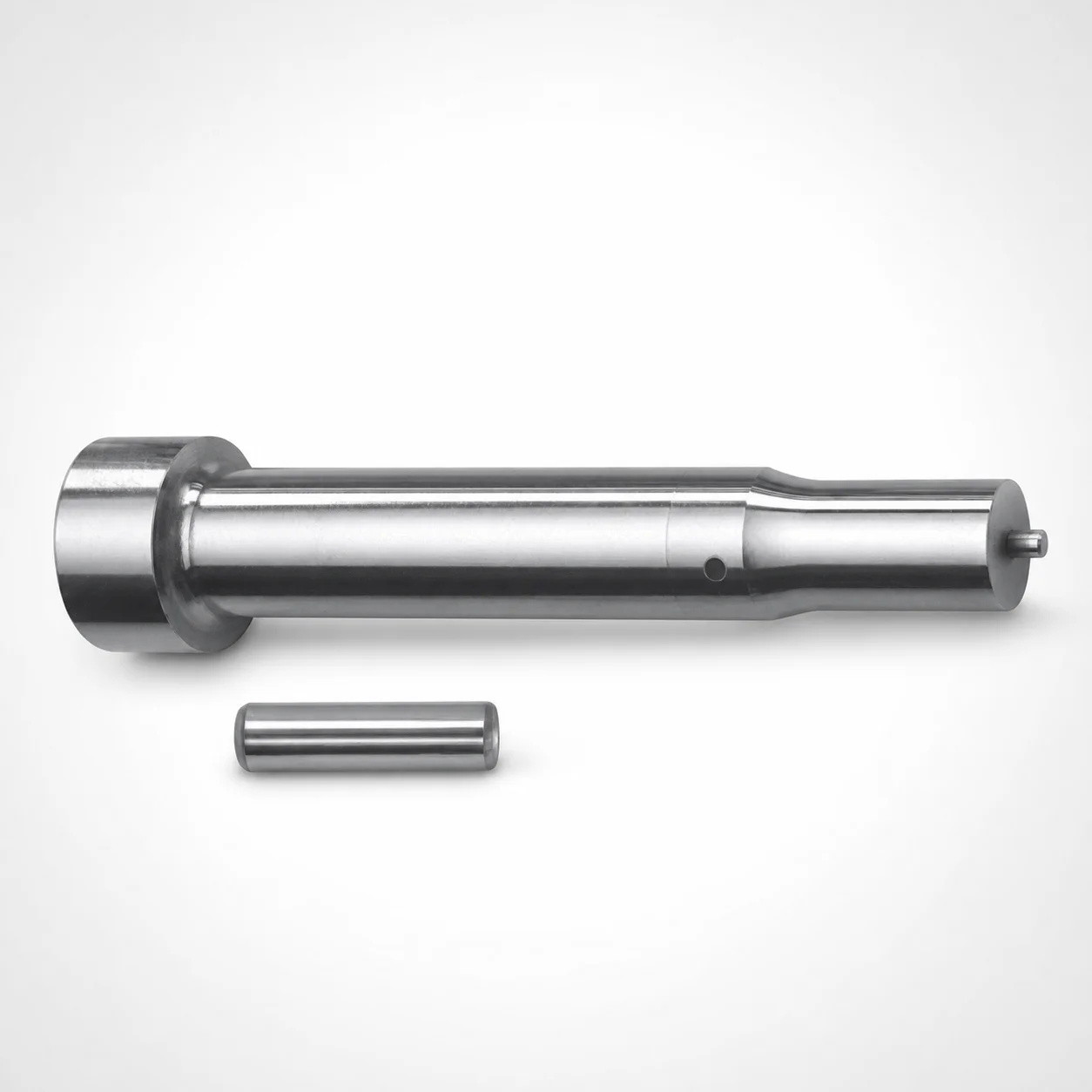
Metric Center Dowel Punches for Heavy Load XNT DayTiN® Coating
Metric center dowel punches for heavy load (XNT DayTiN® coating) are designed for stable die alignment and long service life in demanding production cycles. Their heavy-load geometry supports consistent positioning during repeated tool operation.
- Heavy-load center dowel punch design for reliable alignment
- XNT DayTiN® coating improves wear performance under molding conditions
- Point and shank tip options for consistent entry and positioning
- Typical use in die casting and injection molding tool assemblies
Specifications
112 configurations available
| Tip shape | D (Shank diameter) (mm) | Jektole group | L1 (Point Length) (mm) | L (Length) (mm) | P Dimension (mm) | W Dimension (mm) | R Dimension (mm) |
|---|---|---|---|---|---|---|---|
| H | 10 | J6M | 13 ~ 19 | 80 ~ 130 | 4 ~ 4.99 | 4 ~ 4.99 | - |
| H | 10 | J6M | 13 ~ 19 | 80 ~ 130 | 4 ~ 4.99 | 5 ~ 10 | - |
| H | 10 | J6M | 13 ~ 19 | 80 ~ 130 | 5 ~ 10 | 4 ~ 4.99 | - |
| H | 10 | J6M | 13 ~ 19 | 80 ~ 130 | 5 ~ 10 | 5 ~ 10 | - |
| H | 13 | J6M | 13 ~ 19 | 80 ~ 130 | 4 ~ 5.99 | 4 ~ 5.99 | - |
| H | 13 | J6M | 13 ~ 19 | 80 ~ 130 | 4 ~ 5.99 | 6 ~ 13 | - |
| H | 13 | J6M | 13 ~ 19 | 80 ~ 130 | 6 ~ 13 | 4 ~ 5.99 | - |
| H | 13 | J6M | 13 ~ 19 | 80 ~ 130 | 6 ~ 13 | 6 ~ 13 | - |
| H | 16 | J9M | 19 ~ 25 | 80 ~ 130 | 6 ~ 16 | 6 ~ 16 | - |
| H | 20 | J9M | 19 ~ 25 | 80 ~ 130 | 6 ~ 20 | 6 ~ 20 | - |
| H | 25 | J9M | 19 ~ 25 | 80 ~ 130 | 6 ~ 25 | 6 ~ 25 | - |
| J | 10 | J6M | 13 ~ 19 | 80 ~ 130 | 4 ~ 4.99 | 4 ~ 4.99 | - |
| J | 10 | J6M | 13 ~ 19 | 80 ~ 130 | 4 ~ 4.99 | 5 ~ 10 | - |
| J | 10 | J6M | 13 ~ 19 | 80 ~ 130 | 5 ~ 10 | 4 ~ 4.99 | - |
| J | 10 | J6M | 13 ~ 19 | 80 ~ 130 | 5 ~ 10 | 5 ~ 10 | - |
| J | 13 | J6M | 13 ~ 19 | 80 ~ 130 | 4 ~ 5.99 | 4 ~ 5.99 | - |
| J | 13 | J6M | 13 ~ 19 | 80 ~ 130 | 4 ~ 5.99 | 6 ~ 13 | - |
| J | 13 | J6M | 13 ~ 19 | 80 ~ 130 | 6 ~ 13 | 4 ~ 5.99 | - |
| J | 13 | J6M | 13 ~ 19 | 80 ~ 130 | 6 ~ 13 | 6 ~ 13 | - |
| J | 16 | J9M | 19 ~ 25 | 80 ~ 130 | 6 ~ 16 | 6 ~ 16 | - |
| J | 20 | J9M | 19 ~ 25 | 80 ~ 130 | 6 ~ 20 | 6 ~ 20 | - |
| J | 25 | J9M | 19 ~ 25 | 80 ~ 130 | 6 ~ 25 | 6 ~ 25 | - |
| K | 10 | J6M | 13 ~ 19 | 80 ~ 130 | 4 ~ 4.99 | 4 ~ 4.99 | 0.2 ~ 5 |
| K | 10 | J6M | 13 ~ 19 | 80 ~ 130 | 4 ~ 4.99 | 5 ~ 10 | 0.2 ~ 5 |
| K | 10 | J6M | 13 ~ 19 | 80 ~ 130 | 5 ~ 10 | 4 ~ 4.99 | 0.2 ~ 5 |
| K | 10 | J6M | 13 ~ 19 | 80 ~ 130 | 5 ~ 10 | 5 ~ 10 | 0.2 ~ 5 |
| K | 13 | J6M | 13 ~ 19 | 80 ~ 130 | 4 ~ 5.99 | 4 ~ 5.99 | 0.2 ~ 6.5 |
| K | 13 | J6M | 13 ~ 19 | 80 ~ 130 | 4 ~ 5.99 | 6 ~ 13 | 0.2 ~ 6.5 |
| K | 13 | J6M | 13 ~ 19 | 80 ~ 130 | 6 ~ 13 | 4 ~ 5.99 | 0.2 ~ 6.5 |
| K | 13 | J6M | 13 ~ 19 | 80 ~ 130 | 6 ~ 13 | 6 ~ 13 | 0.2 ~ 6.5 |
| K | 16 | J9M | 19 ~ 25 | 80 ~ 130 | 6 ~ 16 | 6 ~ 16 | 0.2 ~ 8 |
| K | 20 | J9M | 19 ~ 25 | 80 ~ 130 | 6 ~ 20 | 6 ~ 20 | 0.2 ~ 10 |
| K | 25 | J9M | 19 ~ 25 | 80 ~ 130 | 6 ~ 25 | 6 ~ 25 | 0.2 ~ 12.5 |
| L | 10 | J6M | 13 ~ 19 | 80 ~ 130 | 4 ~ 4.99 | 4 ~ 4.99 | - |
| L | 10 | J6M | 13 ~ 19 | 80 ~ 130 | 4 ~ 4.99 | 5 ~ 10 | - |
| L | 10 | J6M | 13 ~ 19 | 80 ~ 130 | 5 ~ 10 | 4 ~ 4.99 | - |
| L | 10 | J6M | 13 ~ 19 | 80 ~ 130 | 5 ~ 10 | 5 ~ 10 | - |
| L | 13 | J6M | 13 ~ 19 | 80 ~ 130 | 4 ~ 5.99 | 4 ~ 5.99 | - |
| L | 13 | J6M | 13 ~ 19 | 80 ~ 130 | 4 ~ 5.99 | 6 ~ 13 | - |
| L | 13 | J6M | 13 ~ 19 | 80 ~ 130 | 6 ~ 13 | 4 ~ 5.99 | - |
| L | 13 | J6M | 13 ~ 19 | 80 ~ 130 | 6 ~ 13 | 6 ~ 13 | - |
| L | 16 | J9M | 19 ~ 25 | 80 ~ 130 | 6 ~ 16 | 6 ~ 16 | - |
| L | 20 | J9M | 19 ~ 25 | 80 ~ 130 | 6 ~ 20 | 6 ~ 20 | - |
| L | 25 | J9M | 19 ~ 25 | 80 ~ 130 | 6 ~ 25 | 6 ~ 25 | - |
| N | 10 | J6M | 13 ~ 19 | 80 ~ 130 | - | 4 ~ 4.99 | - |
| N | 10 | J6M | 13 ~ 19 | 80 ~ 130 | - | 5 ~ 10 | - |
| N | 13 | J6M | 13 ~ 19 | 80 ~ 130 | - | 4 ~ 5.99 | - |
| N | 13 | J6M | 13 ~ 19 | 80 ~ 130 | - | 6 ~ 13 | - |
| N | 16 | J9M | 19 ~ 25 | 80 ~ 130 | - | 6 ~ 16 | - |
| N | 20 | J9M | 19 ~ 25 | 80 ~ 130 | - | 6 ~ 20 | - |
Product Guide
Application Scenarios+
Metric center dowel punches for heavy-load tool alignment are used to maintain repeatable positioning between mold halves and mating components, especially where high clamping force or frequent cycling can otherwise introduce alignment drift.
- Automotive and appliance die casting: In die casting tool sets, the heavy-load geometry supports stable centerline registration during repeated ejection and shot cycles. The XNT DayTiN® coating helps resist wear from sliding contact at the interface.
- Injection molding with long production runs: For large-part injection molding assemblies, these punches support consistent cavity alignment by providing a reliable guide entry. The available shank diameter D options (10–25 mm) and controlled point length support predictable engagement.
- High-cycle sub-assemblies: When rapid parting/closing movement increases fretting risk, the wear-focused coating and configurable tip shapes help maintain fit stability over time.
Choose this variant when you need heavy-load alignment performance and improved wear resistance at the dowel engagement region.
Material & Process Details+
The provided specifications focus on dimensional compatibility and an XNT DayTiN® surface coating, which is intended to improve wear resistance under molding/die casting contact conditions. However, no underlying steel grade, bulk hardness (HRC), or specific heat-treatment state (e.g., quench & temper, nitriding) is included in the input data.
For engineers comparing options, coating characteristics typically trade wear resistance for cost and, in some cases, slight changes in effective surface friction or sizing due to coating thickness. Without the base material grade and heat-treatment parameters, hardness/toughness comparisons between steel variants cannot be verified from the supplied information.
- Coating: XNT DayTiN® for improved wear performance
- Heat treatment: Not specified in the provided data
- Hardness (HRC): Not specified in the provided data
Confirm the substrate grade and heat-treatment through the product documentation set if you require HRC verification for your tool stress profile.
Sizing & Selection Guide+
Select dimensions by matching the dowel punch to the mating bore/core pocket in your mold assembly so engagement is consistent across cycles.
- Shank diameter (D): Choose one of the available sizes D = 10, 13, 16, 20, 25 mm to match the receiving hole size in the moving/immobile half according to your design drawings.
- Overall length (L): Use L = 80–130 mm to ensure adequate guidance length for your mold thickness and parting stroke.
- Point length (L1): Select from 13–19 mm or 19–25 mm based on the desired initial contact zone and the available lead-in depth.
- Tip shape: Pick H, J, K, L, N, O, R, V, X, Y, or Z to suit the entry geometry used in your dowel pocket and to control how the punch starts alignment.
Control fit by ensuring your dowel bore clearance/interference design accounts for the XNT DayTiN® coating surface. Tolerance values are not provided in the input data, so use your internal GD&T and supplier tolerance sheet when finalizing hole/punch mating.
Frequently Asked Questions
Which shank diameter (D) options are available for these heavy-load metric center dowel punches?+
The available shank diameter D values are 10, 13, 16, 20, and 25 mm. Select the diameter to match the dowel receiving bore size in your mold halves so guidance remains repeatable under load.
How do I choose the point length (L1) and overall length (L) for a specific mold thickness?+
Overall length L is 80–130 mm, and point length L1 is 13–19 mm or 19–25 mm. Choose L to provide sufficient guidance length across the mold thickness, and choose L1 to ensure reliable lead-in/contact based on the dowel pocket depth.
What tip shapes are supported, and how do they relate to entry behavior during tool closing?+
Tip shape options are H, J, K, L, N, O, R, V, X, Y, Z. The tip shape selection should match your receiving geometry to control how the punch enters and centers during closing, improving alignment stability during repeated cycles.
What is the meaning of the Jektole group (J6M, J9M) for this punch series?+
This series lists Jektole group options as J6M and J9M. Use the group code to align with your intended fit/guide system and the mating component specification; the input data does not define the dimensional tolerances behind each group, so verify against the tolerance documentation.
Does the XNT DayTiN® coating affect sizing/fit, and what should I verify before releasing drawings?+
The product specifies an XNT DayTiN® coating for improved wear resistance, which can influence the effective surface size at the engagement region. Because coating thickness and tolerance values are not provided in the input data, confirm the coating specification and the applicable tolerance sheet before finalizing hole/punch mating dimensions.
Related Products

Metric Dowel Punches for Heavy Load with Single-Stepped Shank (M5)

Metric Center Dowel Punches for Heavy Load TiCN Coated

JIS Standard SKH51 Steel Ejector Punches for Heavy Load with Dowel Holes

SKH51 Steel TiCN Coating Ejector Punches for Heavy Load with Dowel Holes

RW Coated Dowel Punches for Heavy Load - Single-Stepped Shank

Center Dowel Ejector Punches for Heavy Load (RW Coating) - SKH51 Steel
Need Custom Specifications?
Our engineering team can help with custom configurations, material selection, and volume pricing.