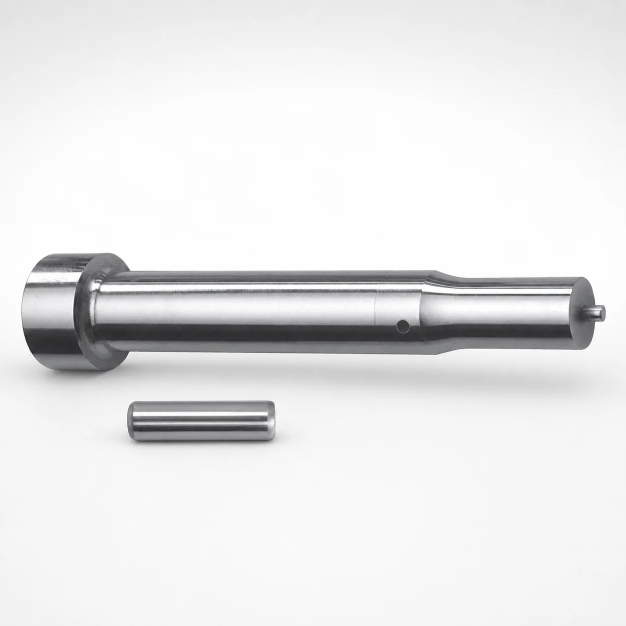
Center Dowel Punches for Heavy Load - Metric (XCDP Coating)
Center Dowel Punches for Heavy Load - Metric (XCDP Coating) are designed for precise centering and reliable dowel seating in heavy-duty mold and die assemblies. The XCDP surface treatment helps reduce wear while supporting consistent performance under repeated operations.
- Heavy-load centering with metric dowel-punch geometry for stable tool alignment
- XCDP coating supports improved wear resistance during punch-dowel engagement
- Flexible tip shapes and shank options accommodate different point-length and fitting needs
- Built for tooling applications requiring accurate positioning and durable center punches
Specifications
112 configurations available
| Tip shape | D (Shank diameter) (mm) | Jektole group | L1 (Point Length) (mm) | L (Length) (mm) | P Dimension (mm) | W Dimension (mm) | R Dimension (mm) |
|---|---|---|---|---|---|---|---|
| H | 10 | J6M | 13 ~ 19 | 80 ~ 130 | 4 ~ 4.99 | 4 ~ 4.99 | - |
| H | 10 | J6M | 13 ~ 19 | 80 ~ 130 | 4 ~ 4.99 | 5 ~ 10 | - |
| H | 10 | J6M | 13 ~ 19 | 80 ~ 130 | 5 ~ 10 | 4 ~ 4.99 | - |
| H | 10 | J6M | 13 ~ 19 | 80 ~ 130 | 5 ~ 10 | 5 ~ 10 | - |
| H | 13 | J6M | 13 ~ 19 | 80 ~ 130 | 4 ~ 5.99 | 4 ~ 5.99 | - |
| H | 13 | J6M | 13 ~ 19 | 80 ~ 130 | 4 ~ 5.99 | 6 ~ 13 | - |
| H | 13 | J6M | 13 ~ 19 | 80 ~ 130 | 6 ~ 13 | 4 ~ 5.99 | - |
| H | 13 | J6M | 13 ~ 19 | 80 ~ 130 | 6 ~ 13 | 6 ~ 13 | - |
| H | 16 | J9M | 19 ~ 25 | 80 ~ 130 | 6 ~ 16 | 6 ~ 16 | - |
| H | 20 | J9M | 19 ~ 25 | 80 ~ 130 | 6 ~ 20 | 6 ~ 20 | - |
| H | 25 | J9M | 19 ~ 25 | 80 ~ 130 | 6 ~ 25 | 6 ~ 25 | - |
| J | 10 | J6M | 13 ~ 19 | 80 ~ 130 | 4 ~ 4.99 | 4 ~ 4.99 | - |
| J | 10 | J6M | 13 ~ 19 | 80 ~ 130 | 4 ~ 4.99 | 5 ~ 10 | - |
| J | 10 | J6M | 13 ~ 19 | 80 ~ 130 | 5 ~ 10 | 4 ~ 4.99 | - |
| J | 10 | J6M | 13 ~ 19 | 80 ~ 130 | 5 ~ 10 | 5 ~ 10 | - |
| J | 13 | J6M | 13 ~ 19 | 80 ~ 130 | 4 ~ 5.99 | 4 ~ 5.99 | - |
| J | 13 | J6M | 13 ~ 19 | 80 ~ 130 | 4 ~ 5.99 | 6 ~ 13 | - |
| J | 13 | J6M | 13 ~ 19 | 80 ~ 130 | 6 ~ 13 | 4 ~ 5.99 | - |
| J | 13 | J6M | 13 ~ 19 | 80 ~ 130 | 6 ~ 13 | 6 ~ 13 | - |
| J | 16 | J9M | 19 ~ 25 | 80 ~ 130 | 6 ~ 16 | 6 ~ 16 | - |
| J | 20 | J9M | 19 ~ 25 | 80 ~ 130 | 6 ~ 20 | 6 ~ 20 | - |
| J | 25 | J9M | 19 ~ 25 | 80 ~ 130 | 6 ~ 25 | 6 ~ 25 | - |
| K | 10 | J6M | 13 ~ 19 | 80 ~ 130 | 4 ~ 4.99 | 4 ~ 4.99 | 0.2 ~ 5 |
| K | 10 | J6M | 13 ~ 19 | 80 ~ 130 | 4 ~ 4.99 | 5 ~ 10 | 0.2 ~ 5 |
| K | 10 | J6M | 13 ~ 19 | 80 ~ 130 | 5 ~ 10 | 4 ~ 4.99 | 0.2 ~ 5 |
| K | 10 | J6M | 13 ~ 19 | 80 ~ 130 | 5 ~ 10 | 5 ~ 10 | 0.2 ~ 5 |
| K | 13 | J6M | 13 ~ 19 | 80 ~ 130 | 4 ~ 5.99 | 4 ~ 5.99 | 0.2 ~ 6.5 |
| K | 13 | J6M | 13 ~ 19 | 80 ~ 130 | 4 ~ 5.99 | 6 ~ 13 | 0.2 ~ 6.5 |
| K | 13 | J6M | 13 ~ 19 | 80 ~ 130 | 6 ~ 13 | 4 ~ 5.99 | 0.2 ~ 6.5 |
| K | 13 | J6M | 13 ~ 19 | 80 ~ 130 | 6 ~ 13 | 6 ~ 13 | 0.2 ~ 6.5 |
| K | 16 | J9M | 19 ~ 25 | 80 ~ 130 | 6 ~ 16 | 6 ~ 16 | 0.2 ~ 8 |
| K | 20 | J9M | 19 ~ 25 | 80 ~ 130 | 6 ~ 20 | 6 ~ 20 | 0.2 ~ 10 |
| K | 25 | J9M | 19 ~ 25 | 80 ~ 130 | 6 ~ 25 | 6 ~ 25 | 0.2 ~ 12.5 |
| L | 10 | J6M | 13 ~ 19 | 80 ~ 130 | 4 ~ 4.99 | 4 ~ 4.99 | - |
| L | 10 | J6M | 13 ~ 19 | 80 ~ 130 | 4 ~ 4.99 | 5 ~ 10 | - |
| L | 10 | J6M | 13 ~ 19 | 80 ~ 130 | 5 ~ 10 | 4 ~ 4.99 | - |
| L | 10 | J6M | 13 ~ 19 | 80 ~ 130 | 5 ~ 10 | 5 ~ 10 | - |
| L | 13 | J6M | 13 ~ 19 | 80 ~ 130 | 4 ~ 5.99 | 4 ~ 5.99 | - |
| L | 13 | J6M | 13 ~ 19 | 80 ~ 130 | 4 ~ 5.99 | 6 ~ 13 | - |
| L | 13 | J6M | 13 ~ 19 | 80 ~ 130 | 6 ~ 13 | 4 ~ 5.99 | - |
| L | 13 | J6M | 13 ~ 19 | 80 ~ 130 | 6 ~ 13 | 6 ~ 13 | - |
| L | 16 | J9M | 19 ~ 25 | 80 ~ 130 | 6 ~ 16 | 6 ~ 16 | - |
| L | 20 | J9M | 19 ~ 25 | 80 ~ 130 | 6 ~ 20 | 6 ~ 20 | - |
| L | 25 | J9M | 19 ~ 25 | 80 ~ 130 | 6 ~ 25 | 6 ~ 25 | - |
| N | 10 | J6M | 13 ~ 19 | 80 ~ 130 | - | 4 ~ 4.99 | - |
| N | 10 | J6M | 13 ~ 19 | 80 ~ 130 | - | 5 ~ 10 | - |
| N | 13 | J6M | 13 ~ 19 | 80 ~ 130 | - | 4 ~ 5.99 | - |
| N | 13 | J6M | 13 ~ 19 | 80 ~ 130 | - | 6 ~ 13 | - |
| N | 16 | J9M | 19 ~ 25 | 80 ~ 130 | - | 6 ~ 16 | - |
| N | 20 | J9M | 19 ~ 25 | 80 ~ 130 | - | 6 ~ 20 | - |
Product Guide
Application Scenarios+
Center dowel punches like this variant are used during injection mold and die builds to lock alignment between cavities, slides, and supporting plates. In heavy-duty tooling, they help establish repeatable “start positions” for dowel seating so parts remain concentric through repeated press cycles.
- Automotive connector and housing molds: Use the heavy-load metric geometry with XCDP coating to maintain stable tool alignment during high-frequency, tight-tolerance insert and connector core alignment.
- Medical device packaging or small-part molds: When centering consistency is critical for repeat cavity spacing, the point-length options (L1 ranges) support correct engagement depth without disturbing established dowel fit.
- Industrial housings and appliance components: For housings requiring durable registration under abrasive conditions, the XCDP surface treatment reduces wear at punch–dowel contact points, supporting longer alignment life.
Material & Process Details+
This series specifies an XCDP coating on a center dowel punch surface to improve wear behavior during punch–dowel engagement in heavy-load tooling. While the provided data does not list the base steel grade or a specific hardness value (HRC), the intent of XCDP is to enhance resistance to surface wear and maintain centering stability over repeated operations.
- Wear resistance vs. toughness: Coated punch surfaces generally prioritize surface hardness and durability, which can improve life at the contact zone while relying on the underlying tool steel for bulk toughness.
- Manufacturing approach: Center dowel punch geometries are formed to metric shank and point dimensions, followed by surface treatment (XCDP) for reduced galling and controlled wear during dowel seating.
If you need exact HRC and heat-treatment state for your build standard, share the intended application load profile; we can align material selection and processing to that requirement.
Sizing & Selection Guide+
Select dimensions by matching the punch tip engagement and shank fit to your core/cavity dowel features. This product is offered in D (shank diameter) values of 10, 13, 16, 20, 25 mm, and a fixed overall L of 80–130 mm depending on the chosen configuration.
- Point length (L1): Choose 13–19 mm or 19–25 mm to set the dowel seating engagement depth without over-penetration. L1 should suit your stack height and the distance to the dowel seating plane.
- Tip shape: Pick from H, J, K, L, N, O, R, V, X, Y, Z to match the mating dowel lead-in geometry and desired centering behavior.
- Fit-related dimensions: Configure P (4–18 mm), W (4–6 mm), and R (0.2–12.5 mm) to match the mating contact profile and required clearance.
Where tolerances and press-fit details depend on your dowel hole spec, validate engagement using your cavity/core datum and account for production tolerances on both punch and dowel bore.
Frequently Asked Questions
Which shank diameter (D) range should I select for heavy-load dowel alignment?+
Choose D based on your mating dowel/receiver feature size. This series supports 10, 13, 16, 20, and 25 mm shank diameters, allowing you to match common heavy-load mold alignment interfaces.
After selecting D, confirm the engagement plane using the chosen L1 range so the punch reaches the dowel seating depth required by your stack-up.
How do I choose between the L1 point-length ranges (13–19 mm vs. 19–25 mm)?+
Select L1 to control how far the punch point reaches into the dowel seating region. Available options are 13–19 mm and 19–25 mm, so you can tune engagement depth to your mold stack height and datum locations.
If you experience bottoming or inadequate seating, adjust L1 rather than changing shank diameter.
Does the XCDP coating change wear performance during punch–dowel engagement?+
The series is specified with XCDP coating to improve wear resistance at the punch surface during repeated engagement. This helps maintain stable centering behavior by reducing wear at the contact zone between the punch point and the dowel features.
For abrasive or high-cycle applications, the XCDP treatment is typically selected to extend alignment life.
How do I select the tip shape (H/J/K/L/N/O/R/V/X/Y/Z) for my dowel lead-in geometry?+
Tip shapes in this series are configurable as H, J, K, L, N, O, R, V, X, Y, Z to suit different lead-in and centering strategies. Match the tip shape to the mating dowel receiver profile so the punch guides the dowel without excessive force.
After choosing tip shape, verify the required engagement depth with L1.
What should I do with P, W, and R dimensions when matching to existing mold drawings?+
Use P (4–18 mm), W (4–6 mm), and R (available ranges include 0.2–5, 0.2–6.5, 0.2–8, 0.2–10, and 0.2–12.5) to replicate the intended contact geometry from your design.
These dimensions influence the punch–dowel contact profile and should be selected to maintain the correct clearance and seating behavior under your mold tolerances.
Related Products

Metric Dowel Punches for Heavy Load with Single-Stepped Shank (M5)

Metric Center Dowel Punches for Heavy Load TiCN Coated

JIS Standard SKH51 Steel Ejector Punches for Heavy Load with Dowel Holes

SKH51 Steel TiCN Coating Ejector Punches for Heavy Load with Dowel Holes

RW Coated Dowel Punches for Heavy Load - Single-Stepped Shank

Center Dowel Ejector Punches for Heavy Load (RW Coating) - SKH51 Steel
Need Custom Specifications?
Our engineering team can help with custom configurations, material selection, and volume pricing.