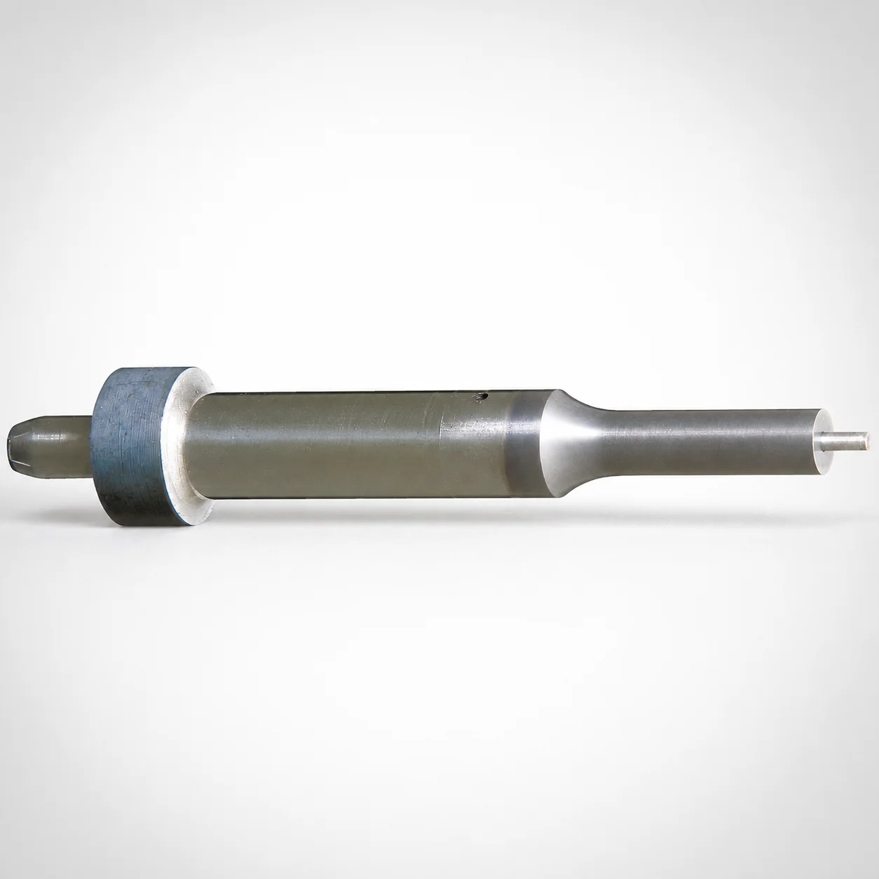
JIS Standard SKH51 Steel Center Dowel Punches for Heavy Load
Center Dowel Punches for Heavy Load (SKH51 steel) use an HW coating to improve wear resistance for stable dowel-hole positioning in high-load die work. The reinforced design supports consistent punch guidance under repeated cycles.
- Heavy-load center punch with locating dowel hole shank mounting for accurate alignment
- HW coating helps reduce friction and extend service life in demanding forming operations
- Single-stepped shank construction supports secure mounting and consistent ejection performance
- Available tip geometries to match tooling layouts for standard and spring/pin reinforced options
Specifications
200 configurations available
| Jector | Tip shape | B (Tip length) | D (Shank diameter) (mm) | P (Tip dimension) (mm) | L (L dimension) (mm) | LC (Full length alteration) (mm) | R (Tip corner R) (mm) | W (Tip dimension) (mm) | type |
|---|---|---|---|---|---|---|---|---|---|
| Standard type | Round | L | 10 | 5 ~ 9.99 | 60 ~ 130 | - | - | - | - |
| Standard type | Round | L | 10 | 5 ~ 9.99 | - | 53 ~ 129.9 | - | - | - |
| Standard type | Round | L | 13 | 6 ~ 12.99 | 60 ~ 130 | - | - | - | - |
| Standard type | Round | L | 13 | 6 ~ 12.99 | - | 53 ~ 129.9 | - | - | - |
| Standard type | Round | L | 16 | 10 ~ 15.99 | 70 ~ 130 | - | - | - | - |
| Standard type | Round | L | 16 | 10 ~ 15.99 | - | 53 ~ 129.9 | - | - | - |
| Standard type | Round | L | 20 | 13 ~ 19.99 | 70 ~ 130 | - | - | - | - |
| Standard type | Round | L | 20 | 13 ~ 19.99 | - | 53 ~ 129.9 | - | - | - |
| Standard type | Round | L | 25 | 18 ~ 24.99 | 70 ~ 130 | - | - | - | - |
| Standard type | Round | L | 25 | 18 ~ 24.99 | - | 53 ~ 129.9 | - | - | - |
| Standard type | Round | S | 10 | 5 ~ 9.99 | 60 ~ 130 | - | - | - | - |
| Standard type | Round | S | 10 | 5 ~ 9.99 | - | 53 ~ 129.9 | - | - | - |
| Standard type | Round | S | 13 | 6 ~ 12.99 | 60 ~ 130 | - | - | - | - |
| Standard type | Round | S | 13 | 6 ~ 12.99 | - | 53 ~ 129.9 | - | - | - |
| Standard type | Round | S | 16 | 10 ~ 15.99 | 60 ~ 130 | - | - | - | - |
| Standard type | Round | S | 16 | 10 ~ 15.99 | - | 53 ~ 129.9 | - | - | - |
| Standard type | Round | S | 20 | 13 ~ 19.99 | 60 ~ 130 | - | - | - | - |
| Standard type | Round | S | 20 | 13 ~ 19.99 | - | 53 ~ 129.9 | - | - | - |
| Standard type | Round | S | 25 | 18 ~ 24.99 | 60 ~ 130 | - | - | - | - |
| Standard type | Round | S | 25 | 18 ~ 24.99 | - | 53 ~ 129.9 | - | - | - |
| Standard type | Rectangle | L | 10 | 5 ~ 9.97 | 60 ~ 130 | - | - | 5 ~ 9.97 | - |
| Standard type | Rectangle | L | 10 | 5 ~ 9.97 | - | 54 ~ 129.9 | - | 5 ~ 9.97 | - |
| Standard type | Rectangle | L | 13 | 6 ~ 12.97 | 60 ~ 130 | - | - | 6 ~ 12.97 | - |
| Standard type | Rectangle | L | 13 | 6 ~ 12.97 | - | 54 ~ 129.9 | - | 6 ~ 12.97 | - |
| Standard type | Rectangle | L | 16 | 6 ~ 15.97 | 70 ~ 130 | - | - | 6 ~ 15.97 | - |
| Standard type | Rectangle | L | 16 | 6 ~ 15.97 | - | 54 ~ 129.9 | - | 6 ~ 15.97 | - |
| Standard type | Rectangle | L | 20 | 6 ~ 19.97 | 70 ~ 130 | - | - | 6 ~ 19.97 | - |
| Standard type | Rectangle | L | 20 | 6 ~ 19.97 | - | 54 ~ 129.9 | - | 6 ~ 19.97 | - |
| Standard type | Rectangle | L | 25 | 6 ~ 24.97 | 70 ~ 130 | - | - | 6 ~ 24.97 | - |
| Standard type | Rectangle | L | 25 | 6 ~ 24.97 | - | 54 ~ 129.9 | - | 6 ~ 24.97 | - |
| Standard type | Rectangle | S | 10 | 5 ~ 9.97 | 60 ~ 130 | - | - | 5 ~ 9.97 | - |
| Standard type | Rectangle | S | 10 | 5 ~ 9.97 | - | 54 ~ 129.9 | - | 5 ~ 9.97 | - |
| Standard type | Rectangle | S | 13 | 6 ~ 12.97 | 60 ~ 130 | - | - | 6 ~ 12.97 | - |
| Standard type | Rectangle | S | 13 | 6 ~ 12.97 | - | 54 ~ 129.9 | - | 6 ~ 12.97 | - |
| Standard type | Rectangle | S | 16 | 6 ~ 15.97 | 60 ~ 130 | - | - | 6 ~ 15.97 | - |
| Standard type | Rectangle | S | 16 | 6 ~ 15.97 | - | 54 ~ 129.9 | - | 6 ~ 15.97 | - |
| Standard type | Rectangle | S | 20 | 6 ~ 19.97 | 60 ~ 130 | - | - | 6 ~ 19.97 | - |
| Standard type | Rectangle | S | 20 | 6 ~ 19.97 | - | 54 ~ 129.9 | - | 6 ~ 19.97 | - |
| Standard type | Rectangle | S | 25 | 6 ~ 24.97 | 60 ~ 130 | - | - | 6 ~ 24.97 | - |
| Standard type | Rectangle | S | 25 | 6 ~ 24.97 | - | 54 ~ 129.9 | - | 6 ~ 24.97 | - |
| Standard type | Oblong | L | 10 | 5 ~ 9.97 | 60 ~ 130 | - | - | 5 ~ 9.97 | - |
| Standard type | Oblong | L | 10 | 5 ~ 9.97 | - | 53 ~ 129.9 | - | 5 ~ 9.97 | - |
| Standard type | Oblong | L | 13 | 6 ~ 12.97 | 60 ~ 130 | - | - | 6 ~ 12.97 | - |
| Standard type | Oblong | L | 13 | 6 ~ 12.97 | - | 53 ~ 129.9 | - | 6 ~ 12.97 | - |
| Standard type | Oblong | L | 16 | 6 ~ 15.97 | 70 ~ 130 | - | - | 6 ~ 15.97 | - |
| Standard type | Oblong | L | 16 | 6 ~ 15.97 | - | 53 ~ 129.9 | - | 6 ~ 15.97 | - |
| Standard type | Oblong | L | 20 | 6 ~ 19.97 | 70 ~ 130 | - | - | 6 ~ 19.97 | - |
| Standard type | Oblong | L | 20 | 6 ~ 19.97 | - | 53 ~ 129.9 | - | 6 ~ 19.97 | - |
| Standard type | Oblong | L | 25 | 6 ~ 24.97 | 70 ~ 130 | - | - | 6 ~ 24.97 | - |
| Standard type | Oblong | L | 25 | 6 ~ 24.97 | - | 53 ~ 129.9 | - | 6 ~ 24.97 | - |
Product Guide
Application Scenarios+
These heavy-load center dowel punches are used in injection mold and die assemblies where reliable dowel-hole positioning is critical under repeated press cycles. The reinforced shank and locating dowel hole support accurate alignment between plates, improving repeatability during start-up and product changeovers.
- Automotive and industrial connector molds: Use the HW-coated SKH51 variant to reduce friction at the punch/guide interface and maintain stable hole-forming performance during high-cadence molding and shutdown cycles.
- Medical device housing tooling: The consistent punch guidance helps form precise dowel locations for tight stack-up control, supporting dimensional stability across multi-cavity molds.
- Appliance and electronics enclosure dies: Select the standard or spring/pin reinforced type to match tooling layouts where higher guidance rigidity is required for long runs.
With multiple shank diameters (10 to 25 mm) and tip geometries (round, rectangle, oblong, double flatted round, radius rectangle), engineers can match the punch to existing cavity/core positioning requirements while leveraging HW coating for reduced wear.
Material & Process Details+
JIS Standard SKH51 center dowel punches are made from a high-speed tool steel commonly selected for guidance components requiring both wear resistance and toughness. In practice, SKH51 is used where elevated cutting/impact-like demands translate into sustained sliding contact and repeated loading at the punch tip.
- Coating: The provided HW coating is intended to lower friction and improve surface wear resistance, supporting stable guidance over long production cycles.
- Heat treatment state: The product is specified as SKH51 steel with HW coating, typically supplied in a hardened condition appropriate for heavy-load punching guidance (verify target hardness range with your supplier/quote).
- Hardness & trade-offs: Higher hardness improves abrasive wear resistance, while excessive hardness without sufficient toughness can increase chipping risk at the tip radius during misalignment.
If you need a brief alternative comparison, SKH51-based guidance balances wear resistance with toughness better than many lower-alloy wear steels, which may wear faster in high-cycle, high-friction guidance interfaces.
Sizing & Selection Guide+
To select the correct center dowel punch, match the shank diameter D and the tip geometry to your mold’s locating features and guide bushings/holes. This series supports D = 10, 13, 16, 20, 25 mm and multiple tip shapes including round, rectangle, oblong, double flatted round, and radius rectangle.
- Tip dimensions (P, W): Choose P = 5 ~ 18 mm and W = 5 ~ 9.97 to 6 ~ 24.97 mm depending on the selected geometry and required dowel-hole profile.
- Length match (L and LC): Select L ranges offered as 60–130, 70–130, 60–100, or 70–100 mm. Then verify the LC (full length alteration) range for your build-up: 53–129.9, 54–129.9, 47–129.9, 53–99.9, or 54–99.9.
- Corner radius (R): Confirm R = 0.15 ~ 4.98 up to 0.15 ~ 12.48 mm to reduce stress concentration at the hole-forming edge.
Fit and tolerance depend on your receiving hole/bushing size and how much clearance is allowed for alignment under load. When changing from standard to spring/pin reinforced types, re-check effective engagement length against LC to maintain consistent stack-up behavior.
Frequently Asked Questions
Which shank diameter options (D) are available for this heavy-load center dowel punch series?+
How do I choose the correct tip geometry and dimensions (P, W, R) for the dowel-hole profile?+
What length parameters (L and LC) should be verified against my mold stack-up?+
What does the HW coating contribute for heavy-load die and mold alignment?+
When should I select the spring/pin reinforced type versus the standard type?+
Related Products

Metric Dowel Punches for Heavy Load with Single-Stepped Shank (M5)

Metric Center Dowel Punches for Heavy Load TiCN Coated

JIS Standard SKH51 Steel Ejector Punches for Heavy Load with Dowel Holes

SKH51 Steel TiCN Coating Ejector Punches for Heavy Load with Dowel Holes

RW Coated Dowel Punches for Heavy Load - Single-Stepped Shank

Center Dowel Ejector Punches for Heavy Load (RW Coating) - SKH51 Steel
Need Custom Specifications?
Our engineering team can help with custom configurations, material selection, and volume pricing.