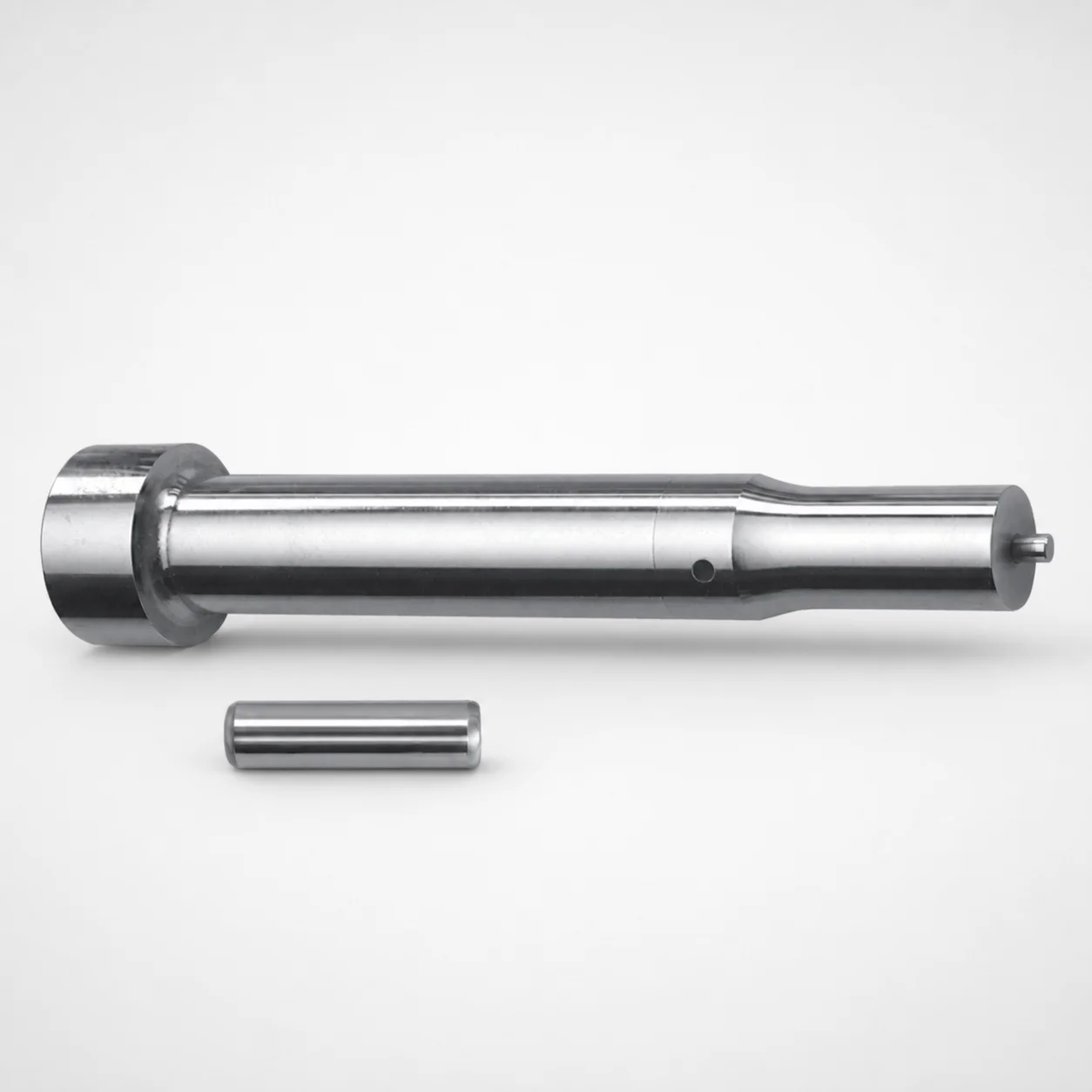
Center Dowel Punches for Heavy Load (Metric) - CRN Coated
Center Dowel Punches for Heavy Load (Metric) (CRN coated) are designed for stable die alignment in demanding molding and tooling setups. The center dowel punch style helps transfer location forces with consistent repeatability, even under heavy load conditions.
- Center dowel punch geometry for accurate die positioning and alignment
- CRN coating improves surface wear resistance for extended service life
- Metric configuration supports compatibility with standard punch/dowel systems
- Heavy-load applications in progressive dies, injection molds, and tooling assemblies
Specifications
112 configurations available
| Tip shape | D (Shank diameter) (mm) | Jektole group | L1 (Point Length) (mm) | L (Length) (mm) | P Dimension (mm) | W Dimension (mm) | R Dimension (mm) |
|---|---|---|---|---|---|---|---|
| H | 10 | J6M | 13 ~ 19 | 80 ~ 130 | 4 ~ 4.99 | 4 ~ 4.99 | - |
| H | 10 | J6M | 13 ~ 19 | 80 ~ 130 | 4 ~ 4.99 | 5 ~ 10 | - |
| H | 10 | J6M | 13 ~ 19 | 80 ~ 130 | 5 ~ 10 | 4 ~ 4.99 | - |
| H | 10 | J6M | 13 ~ 19 | 80 ~ 130 | 5 ~ 10 | 5 ~ 10 | - |
| H | 13 | J6M | 13 ~ 19 | 80 ~ 130 | 4 ~ 5.99 | 4 ~ 5.99 | - |
| H | 13 | J6M | 13 ~ 19 | 80 ~ 130 | 4 ~ 5.99 | 6 ~ 13 | - |
| H | 13 | J6M | 13 ~ 19 | 80 ~ 130 | 6 ~ 13 | 4 ~ 5.99 | - |
| H | 13 | J6M | 13 ~ 19 | 80 ~ 130 | 6 ~ 13 | 6 ~ 13 | - |
| H | 16 | J9M | 19 ~ 25 | 80 ~ 130 | 6 ~ 16 | 6 ~ 16 | - |
| H | 20 | J9M | 19 ~ 25 | 80 ~ 130 | 6 ~ 20 | 6 ~ 20 | - |
| H | 25 | J9M | 19 ~ 25 | 80 ~ 130 | 6 ~ 25 | 6 ~ 25 | - |
| J | 10 | J6M | 13 ~ 19 | 80 ~ 130 | 4 ~ 4.99 | 4 ~ 4.99 | - |
| J | 10 | J6M | 13 ~ 19 | 80 ~ 130 | 4 ~ 4.99 | 5 ~ 10 | - |
| J | 10 | J6M | 13 ~ 19 | 80 ~ 130 | 5 ~ 10 | 4 ~ 4.99 | - |
| J | 10 | J6M | 13 ~ 19 | 80 ~ 130 | 5 ~ 10 | 5 ~ 10 | - |
| J | 13 | J6M | 13 ~ 19 | 80 ~ 130 | 4 ~ 5.99 | 4 ~ 5.99 | - |
| J | 13 | J6M | 13 ~ 19 | 80 ~ 130 | 4 ~ 5.99 | 6 ~ 13 | - |
| J | 13 | J6M | 13 ~ 19 | 80 ~ 130 | 6 ~ 13 | 4 ~ 5.99 | - |
| J | 13 | J6M | 13 ~ 19 | 80 ~ 130 | 6 ~ 13 | 6 ~ 13 | - |
| J | 16 | J9M | 19 ~ 25 | 80 ~ 130 | 6 ~ 16 | 6 ~ 16 | - |
| J | 20 | J9M | 19 ~ 25 | 80 ~ 130 | 6 ~ 20 | 6 ~ 20 | - |
| J | 25 | J9M | 19 ~ 25 | 80 ~ 130 | 6 ~ 25 | 6 ~ 25 | - |
| K | 10 | J6M | 13 ~ 19 | 80 ~ 130 | 4 ~ 4.99 | 4 ~ 4.99 | 0.2 ~ 5 |
| K | 10 | J6M | 13 ~ 19 | 80 ~ 130 | 4 ~ 4.99 | 5 ~ 10 | 0.2 ~ 5 |
| K | 10 | J6M | 13 ~ 19 | 80 ~ 130 | 5 ~ 10 | 4 ~ 4.99 | 0.2 ~ 5 |
| K | 10 | J6M | 13 ~ 19 | 80 ~ 130 | 5 ~ 10 | 5 ~ 10 | 0.2 ~ 5 |
| K | 13 | J6M | 13 ~ 19 | 80 ~ 130 | 4 ~ 5.99 | 4 ~ 5.99 | 0.2 ~ 6.5 |
| K | 13 | J6M | 13 ~ 19 | 80 ~ 130 | 4 ~ 5.99 | 6 ~ 13 | 0.2 ~ 6.5 |
| K | 13 | J6M | 13 ~ 19 | 80 ~ 130 | 6 ~ 13 | 4 ~ 5.99 | 0.2 ~ 6.5 |
| K | 13 | J6M | 13 ~ 19 | 80 ~ 130 | 6 ~ 13 | 6 ~ 13 | 0.2 ~ 6.5 |
| K | 16 | J9M | 19 ~ 25 | 80 ~ 130 | 6 ~ 16 | 6 ~ 16 | 0.2 ~ 8 |
| K | 20 | J9M | 19 ~ 25 | 80 ~ 130 | 6 ~ 20 | 6 ~ 20 | 0.2 ~ 10 |
| K | 25 | J9M | 19 ~ 25 | 80 ~ 130 | 6 ~ 25 | 6 ~ 25 | 0.2 ~ 12.5 |
| L | 10 | J6M | 13 ~ 19 | 80 ~ 130 | 4 ~ 4.99 | 4 ~ 4.99 | - |
| L | 10 | J6M | 13 ~ 19 | 80 ~ 130 | 4 ~ 4.99 | 5 ~ 10 | - |
| L | 10 | J6M | 13 ~ 19 | 80 ~ 130 | 5 ~ 10 | 4 ~ 4.99 | - |
| L | 10 | J6M | 13 ~ 19 | 80 ~ 130 | 5 ~ 10 | 5 ~ 10 | - |
| L | 13 | J6M | 13 ~ 19 | 80 ~ 130 | 4 ~ 5.99 | 4 ~ 5.99 | - |
| L | 13 | J6M | 13 ~ 19 | 80 ~ 130 | 4 ~ 5.99 | 6 ~ 13 | - |
| L | 13 | J6M | 13 ~ 19 | 80 ~ 130 | 6 ~ 13 | 4 ~ 5.99 | - |
| L | 13 | J6M | 13 ~ 19 | 80 ~ 130 | 6 ~ 13 | 6 ~ 13 | - |
| L | 16 | J9M | 19 ~ 25 | 80 ~ 130 | 6 ~ 16 | 6 ~ 16 | - |
| L | 20 | J9M | 19 ~ 25 | 80 ~ 130 | 6 ~ 20 | 6 ~ 20 | - |
| L | 25 | J9M | 19 ~ 25 | 80 ~ 130 | 6 ~ 25 | 6 ~ 25 | - |
| N | 10 | J6M | 13 ~ 19 | 80 ~ 130 | - | 4 ~ 4.99 | - |
| N | 10 | J6M | 13 ~ 19 | 80 ~ 130 | - | 5 ~ 10 | - |
| N | 13 | J6M | 13 ~ 19 | 80 ~ 130 | - | 4 ~ 5.99 | - |
| N | 13 | J6M | 13 ~ 19 | 80 ~ 130 | - | 6 ~ 13 | - |
| N | 16 | J9M | 19 ~ 25 | 80 ~ 130 | - | 6 ~ 16 | - |
| N | 20 | J9M | 19 ~ 25 | 80 ~ 130 | - | 6 ~ 20 | - |
Product Guide
Application Scenarios+
This heavy-load center dowel punch is used to lock die halves and guide alignment during injection molding and related tooling operations. Its center dowel geometry supports reliable location under repeated starts/stops, helping reduce misalignment that can lead to flash, uneven cavity shutoff, or progressive die drift.
- Automotive and industrial connector molds: Suitable for long production runs where high clamp force and frequent cycling demand consistent positional repeatability; the CRN-coated contact surfaces help resist wear on alignment areas.
- Progressive stamping/die sets for metal inserts: Used as a locating element to transfer positioning loads while maintaining alignment across multiple stations; the heavy-load punch form supports stable die positioning.
- Medical device housing or precision component tooling: Helps maintain tight assembly alignment in multi-part tooling; metric configuration supports compatibility with common punch/dowel systems used in die alignment fixtures.
Choose the appropriate shank diameter and point length to match the engagement depth and load path required by the cavity/core layout.
Material & Process Details+
The provided specifications identify the CRN-coated variant, which is selected primarily for improved surface wear resistance on the alignment/contact areas of the punch. The coating is intended to reduce abrasive and sliding wear during repeated die closures, supporting longer service life compared with uncoated alignment pins in heavy-duty cycles.
- Wear resistance vs. toughness trade-off: CRN coatings generally improve surface hardness and wear behavior, while the underlying steel must still provide sufficient core toughness to avoid chipping at the tip and point edges under high load.
- Heat treatment state: Not specified in the input data; however, heavy-load dowel punches for tooling are typically manufactured from hardened tool steels with a final tempering step to balance stiffness and toughness.
Because the base steel grade and exact hardness (HRC) are not included in the provided information, hardness and heat-treatment specifics should be confirmed against the item’s manufacturing certificate for the selected tip shape and dimensions.
Sizing & Selection Guide+
To select the correct center dowel punch, match engagement and alignment geometry to your die alignment system. Start by choosing the D (shank diameter) from 10, 13, 16, 20, or 25 mm to fit your mating bushing or die insert bore requirements.
- Overall length (L): Fixed at 80 to 130 mm. Select based on the required stand-off and how far the punch must extend through the die components.
- Point/tip length (L1): Choose 13–19 mm or 19–25 mm to ensure adequate point engagement without bottoming.
- Tip shape: Select H, J, K, L, N, O, R, V, X, Y, or Z to match the guiding profile and the lead-in features of your complementary alignment hole.
Confirm also related geometry parameters: P = 4–18 mm, W = 4–6 mm, and R = 0.2–5 to 0.2–12.5 mm depending on the chosen configuration. Tolerance and fit are not listed in the input; therefore, validate mating clearance/interference with your die bore tolerances and wear allowance for the selected CRN-coated surface.
Frequently Asked Questions
Which shank diameter (D) should I choose to match my die bushing bore for heavy-load alignment?+
What range of point length (L1) and overall length (L) should be used to achieve stable engagement without bottoming?+
How does the CRN coating benefit heavy-load die alignment, and is it meant for wear surfaces?+
How do I select the correct tip shape (H, J, K, L, N, O, R, V, X, Y, Z) for my alignment hole lead-in?+
What should I check for P, W, and R dimensions when comparing this punch to an existing design?+
Related Products

Metric Dowel Punches for Heavy Load with Single-Stepped Shank (M5)

Metric Center Dowel Punches for Heavy Load TiCN Coated

JIS Standard SKH51 Steel Ejector Punches for Heavy Load with Dowel Holes

SKH51 Steel TiCN Coating Ejector Punches for Heavy Load with Dowel Holes

RW Coated Dowel Punches for Heavy Load - Single-Stepped Shank

Center Dowel Ejector Punches for Heavy Load (RW Coating) - SKH51 Steel
Need Custom Specifications?
Our engineering team can help with custom configurations, material selection, and volume pricing.