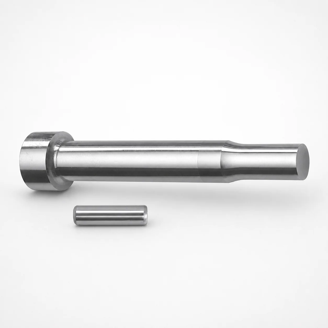
Metric XVP Coated Center Dowel Punches for Heavy Load
Center Dowel Punches for Heavy Load (Metric, XVP coated) are engineered for reliable workpiece alignment in progressive dies and heavy-duty tooling. The center locating geometry supports consistent positioning under load.
- Heavy-load center dowel punch design for stable locating during repeated press cycles
- XVP coating to improve wear resistance and help maintain pointing performance
- Multiple tip shapes available (X, R, K, O, H, L, J, N, V, Y, Z) to match die features
- Metric configuration suitable for general die maintenance and replacement in production lines
Specifications
164 configurations available
| Tip shape | D (Shank diameter) (mm) | L1 (Point Length) (mm) | L (Length) (mm) | P Dimension (mm) | W Dimension (mm) | R Dimension (mm) |
|---|---|---|---|---|---|---|
| H | 10 | 13 ~ 19 | 80 ~ 130 | 1.5 ~ 2.99 | 1.5 ~ 2.99 | - |
| H | 10 | 13 ~ 19 | 80 ~ 130 | 1.5 ~ 2.99 | 3 ~ 10 | - |
| H | 10 | 13 ~ 19 | 80 ~ 130 | 3 ~ 10 | 1.5 ~ 2.99 | - |
| H | 10 | 13 ~ 19 | 80 ~ 130 | 3 ~ 10 | 3 ~ 10 | - |
| H | 13 | 13 ~ 19 | 80 ~ 130 | 1.5 ~ 2.99 | 1.5 ~ 2.99 | - |
| H | 13 | 13 ~ 19 | 80 ~ 130 | 1.5 ~ 2.99 | 3 ~ 13 | - |
| H | 13 | 13 ~ 19 | 80 ~ 130 | 3 ~ 13 | 1.5 ~ 2.99 | - |
| H | 13 | 13 ~ 19 | 80 ~ 130 | 3 ~ 13 | 3 ~ 13 | - |
| H | 16 | 19 ~ 25 | 80 ~ 130 | 3 ~ 3.99 | 3 ~ 3.99 | - |
| H | 16 | 19 ~ 25 | 80 ~ 130 | 3 ~ 3.99 | 4 ~ 16 | - |
| H | 16 | 19 ~ 25 | 80 ~ 130 | 4 ~ 16 | 3 ~ 3.99 | - |
| H | 16 | 19 ~ 25 | 80 ~ 130 | 4 ~ 16 | 4 ~ 16 | - |
| H | 20 | 19 ~ 25 | 80 ~ 130 | 3 ~ 4.99 | 3 ~ 4.99 | - |
| H | 20 | 19 ~ 25 | 80 ~ 130 | 3 ~ 4.99 | 5 ~ 20 | - |
| H | 20 | 19 ~ 25 | 80 ~ 130 | 5 ~ 20 | 3 ~ 4.99 | - |
| H | 20 | 19 ~ 25 | 80 ~ 130 | 5 ~ 20 | 5 ~ 20 | - |
| H | 25 | 19 ~ 25 | 80 ~ 130 | 6 ~ 25 | 6 ~ 25 | - |
| J | 10 | 13 ~ 19 | 80 ~ 130 | 1.5 ~ 2.99 | 1.5 ~ 2.99 | - |
| J | 10 | 13 ~ 19 | 80 ~ 130 | 1.5 ~ 2.99 | 3 ~ 10 | - |
| J | 10 | 13 ~ 19 | 80 ~ 130 | 3 ~ 10 | 1.5 ~ 2.99 | - |
| J | 10 | 13 ~ 19 | 80 ~ 130 | 3 ~ 10 | 3 ~ 10 | - |
| J | 13 | 13 ~ 19 | 80 ~ 130 | 1.5 ~ 2.99 | 1.5 ~ 2.99 | - |
| J | 13 | 13 ~ 19 | 80 ~ 130 | 1.5 ~ 2.99 | 3 ~ 13 | - |
| J | 13 | 13 ~ 19 | 80 ~ 130 | 3 ~ 13 | 1.5 ~ 2.99 | - |
| J | 13 | 13 ~ 19 | 80 ~ 130 | 3 ~ 13 | 3 ~ 13 | - |
| J | 16 | 19 ~ 25 | 80 ~ 130 | 3 ~ 3.99 | 3 ~ 3.99 | - |
| J | 16 | 19 ~ 25 | 80 ~ 130 | 3 ~ 3.99 | 4 ~ 16 | - |
| J | 16 | 19 ~ 25 | 80 ~ 130 | 4 ~ 16 | 3 ~ 3.99 | - |
| J | 16 | 19 ~ 25 | 80 ~ 130 | 4 ~ 16 | 4 ~ 16 | - |
| J | 20 | 19 ~ 25 | 80 ~ 130 | 3 ~ 4.99 | 3 ~ 4.99 | - |
| J | 20 | 19 ~ 25 | 80 ~ 130 | 3 ~ 4.99 | 5 ~ 20 | - |
| J | 20 | 19 ~ 25 | 80 ~ 130 | 5 ~ 20 | 3 ~ 4.99 | - |
| J | 20 | 19 ~ 25 | 80 ~ 130 | 5 ~ 20 | 5 ~ 20 | - |
| J | 25 | 19 ~ 25 | 80 ~ 130 | 6 ~ 25 | 6 ~ 25 | - |
| K | 10 | 13 ~ 19 | 80 ~ 130 | 1.5 ~ 2.99 | 1.5 ~ 2.99 | 0.2 ~ 5 |
| K | 10 | 13 ~ 19 | 80 ~ 130 | 1.5 ~ 2.99 | 3 ~ 10 | 0.2 ~ 5 |
| K | 10 | 13 ~ 19 | 80 ~ 130 | 3 ~ 10 | 1.5 ~ 2.99 | 0.2 ~ 5 |
| K | 10 | 13 ~ 19 | 80 ~ 130 | 3 ~ 10 | 3 ~ 10 | 0.2 ~ 5 |
| K | 13 | 13 ~ 19 | 80 ~ 130 | 1.5 ~ 2.99 | 1.5 ~ 2.99 | 0.2 ~ 6.5 |
| K | 13 | 13 ~ 19 | 80 ~ 130 | 1.5 ~ 2.99 | 3 ~ 13 | 0.2 ~ 6.5 |
| K | 13 | 13 ~ 19 | 80 ~ 130 | 3 ~ 13 | 1.5 ~ 2.99 | 0.2 ~ 6.5 |
| K | 13 | 13 ~ 19 | 80 ~ 130 | 3 ~ 13 | 3 ~ 13 | 0.2 ~ 6.5 |
| K | 16 | 19 ~ 25 | 80 ~ 130 | 3 ~ 3.99 | 3 ~ 3.99 | 0.2 ~ 8 |
| K | 16 | 19 ~ 25 | 80 ~ 130 | 3 ~ 3.99 | 4 ~ 16 | 0.2 ~ 8 |
| K | 16 | 19 ~ 25 | 80 ~ 130 | 4 ~ 16 | 3 ~ 3.99 | 0.2 ~ 8 |
| K | 16 | 19 ~ 25 | 80 ~ 130 | 4 ~ 16 | 4 ~ 16 | 0.2 ~ 8 |
| K | 20 | 19 ~ 25 | 80 ~ 130 | 3 ~ 4.99 | 3 ~ 4.99 | 0.2 ~ 10 |
| K | 20 | 19 ~ 25 | 80 ~ 130 | 3 ~ 4.99 | 5 ~ 20 | 0.2 ~ 10 |
| K | 20 | 19 ~ 25 | 80 ~ 130 | 5 ~ 20 | 3 ~ 4.99 | 0.2 ~ 10 |
| K | 20 | 19 ~ 25 | 80 ~ 130 | 5 ~ 20 | 5 ~ 20 | 0.2 ~ 10 |
Product Guide
Application Scenarios+
Metric center dowel punches for heavy-load tooling are used to reference and stabilize workpiece position during repeated press cycles, especially in progressive dies and alignment-critical stamping operations. The heavy-duty center locating geometry helps maintain consistent pointing performance even when loads rise across long production runs.
- Progressive stamping and carrier dies: Use the chosen tip shape (X, R, K, O, H, L, J, N, V, Y, Z) to match receiver/guiding features and reduce misalignment under load.
- Automotive-grade bracket and connector housings: The XVP coating supports wear resistance at the locating interface, helping retain accurate alignment as cavity components cycle.
- Die maintenance and component replacement: Metric shank diameters (D = 10–25 mm) and point length ranges (L1 = 13–25 mm) simplify replacement while preserving center positioning geometry.
This variant’s XVP coating and heavy-load locating design make it well-suited for tooling where alignment drift and point wear directly affect part dimensional stability.
Material & Process Details+
The provided configuration specifies an XVP coated center dowel punch, with the emphasis on coating-driven wear performance at the locating tip. While the exact base steel grade and heat-treatment condition are not listed in the input data, the intent of XVP for punch interfaces is to improve surface wear resistance and help maintain pointing performance over repeated cycles.
- Wear vs. toughness balance: Locating punches experience high contact pressure at the point; a harder, wear-optimized surface (via coating) supports dimensional stability while the underlying body maintains necessary toughness for repeated mechanical loading.
- Coating impact: XVP coating is selected to reduce point and edge wear that can lead to alignment drift.
- Material comparisons: If alternate steels are offered for different die environments, selection typically trades wear resistance for shock/toughness, but those specific options are not provided here.
For exact HRC and heat treatment state, confirm the base material grade for series 250301835266 before final die design sign-off.
Sizing & Selection Guide+
Select dimensions by matching the punch geometry to the die’s mating bushing/hole and the receiver feature on your locating system. This series uses a fixed overall L = 80–130 mm, while several critical dimensions are variable to adapt to different die layouts.
- Shank diameter (D): Choose D = 10, 13, 16, 20, or 25 mm to fit the corresponding center-locator bore with appropriate clearance.
- Point length (L1): Match the available receiver engagement length: L1 = 13–19 mm or 19–25 mm.
- Tip shape: Select the tip shape (H, J, K, L, N, O, R, V, X, Y, Z) that corresponds to the die feature geometry to avoid stress concentration and ensure repeatable locating.
- Geometric details: Verify P = 1.5–18 mm and W = 1.5–6 mm, and confirm the applicable R range (e.g., R = 0.2–5 up to 0.2–12.5 mm depending on variant).
Because XVP coating thickness and mating tolerances affect contact behavior, validate clearance and engagement depth during dry-fit; maintain consistent seating so the center line repeats under load.
Frequently Asked Questions
Which tip shapes (H, J, K, L, N, O, R, V, X, Y, Z) should I select for a specific center-locating feature in a progressive die?+
How do I choose the correct shank diameter D for the dowel punch bore?+
What point length L1 ranges are available, and how does L1 affect locating engagement?+
What dimensional checks are most important for the P, W, and R features in this series?+
Does the XVP coating improve locating wear performance in heavy-load stamping?+
Related Products

Metric Dowel Punches for Heavy Load with Single-Stepped Shank (M5)

Metric Center Dowel Punches for Heavy Load TiCN Coated

JIS Standard SKH51 Steel Ejector Punches for Heavy Load with Dowel Holes

SKH51 Steel TiCN Coating Ejector Punches for Heavy Load with Dowel Holes

RW Coated Dowel Punches for Heavy Load - Single-Stepped Shank

Center Dowel Ejector Punches for Heavy Load (RW Coating) - SKH51 Steel
Need Custom Specifications?
Our engineering team can help with custom configurations, material selection, and volume pricing.