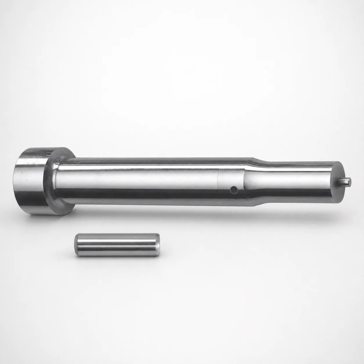
Center Dowel Punches for Heavy Load - Metric, XNP Coating
Center Dowel Punches for Heavy Load - Metric, XNP Coating are designed to accurately position workpieces and support high repeatability in heavy duty die and fixture setups. The XNP coating helps improve surface durability where regular contact and sliding occur.
- Center dowel punch tip supports reliable registration of dowel holes in heavy load applications
- XNP coating enhances wear resistance for consistent performance over repeated cycles
- Metric design supports precise fit and repeatable alignment during assembly and production
- DAYTON LAMINA standardized part number format streamlines specification matching across orders
Specifications
112 configurations available
| Tip shape | D (Shank diameter) (mm) | Jektole group | L1 (Point Length) (mm) | L (Length) (mm) | P Dimension (mm) | W Dimension (mm) | R Dimension (mm) |
|---|---|---|---|---|---|---|---|
| H | 10 | J6M | 13 ~ 19 | 80 ~ 130 | 4 ~ 4.99 | 4 ~ 4.99 | - |
| H | 10 | J6M | 13 ~ 19 | 80 ~ 130 | 4 ~ 4.99 | 5 ~ 10 | - |
| H | 10 | J6M | 13 ~ 19 | 80 ~ 130 | 5 ~ 10 | 4 ~ 4.99 | - |
| H | 10 | J6M | 13 ~ 19 | 80 ~ 130 | 5 ~ 10 | 5 ~ 10 | - |
| H | 13 | J6M | 13 ~ 19 | 80 ~ 130 | 4 ~ 5.99 | 4 ~ 5.99 | - |
| H | 13 | J6M | 13 ~ 19 | 80 ~ 130 | 4 ~ 5.99 | 6 ~ 13 | - |
| H | 13 | J6M | 13 ~ 19 | 80 ~ 130 | 6 ~ 13 | 4 ~ 5.99 | - |
| H | 13 | J6M | 13 ~ 19 | 80 ~ 130 | 6 ~ 13 | 6 ~ 13 | - |
| H | 16 | J9M | 19 ~ 25 | 80 ~ 130 | 6 ~ 16 | 6 ~ 16 | - |
| H | 20 | J9M | 19 ~ 25 | 80 ~ 130 | 6 ~ 20 | 6 ~ 20 | - |
| H | 25 | J9M | 19 ~ 25 | 80 ~ 130 | 6 ~ 25 | 6 ~ 25 | - |
| J | 10 | J6M | 13 ~ 19 | 80 ~ 130 | 4 ~ 4.99 | 4 ~ 4.99 | - |
| J | 10 | J6M | 13 ~ 19 | 80 ~ 130 | 4 ~ 4.99 | 5 ~ 10 | - |
| J | 10 | J6M | 13 ~ 19 | 80 ~ 130 | 5 ~ 10 | 4 ~ 4.99 | - |
| J | 10 | J6M | 13 ~ 19 | 80 ~ 130 | 5 ~ 10 | 5 ~ 10 | - |
| J | 13 | J6M | 13 ~ 19 | 80 ~ 130 | 4 ~ 5.99 | 4 ~ 5.99 | - |
| J | 13 | J6M | 13 ~ 19 | 80 ~ 130 | 4 ~ 5.99 | 6 ~ 13 | - |
| J | 13 | J6M | 13 ~ 19 | 80 ~ 130 | 6 ~ 13 | 4 ~ 5.99 | - |
| J | 13 | J6M | 13 ~ 19 | 80 ~ 130 | 6 ~ 13 | 6 ~ 13 | - |
| J | 16 | J9M | 19 ~ 25 | 80 ~ 130 | 6 ~ 16 | 6 ~ 16 | - |
| J | 20 | J9M | 19 ~ 25 | 80 ~ 130 | 6 ~ 20 | 6 ~ 20 | - |
| J | 25 | J9M | 19 ~ 25 | 80 ~ 130 | 6 ~ 25 | 6 ~ 25 | - |
| K | 10 | J6M | 13 ~ 19 | 80 ~ 130 | 4 ~ 4.99 | 4 ~ 4.99 | 0.2 ~ 5 |
| K | 10 | J6M | 13 ~ 19 | 80 ~ 130 | 4 ~ 4.99 | 5 ~ 10 | 0.2 ~ 5 |
| K | 10 | J6M | 13 ~ 19 | 80 ~ 130 | 5 ~ 10 | 4 ~ 4.99 | 0.2 ~ 5 |
| K | 10 | J6M | 13 ~ 19 | 80 ~ 130 | 5 ~ 10 | 5 ~ 10 | 0.2 ~ 5 |
| K | 13 | J6M | 13 ~ 19 | 80 ~ 130 | 4 ~ 5.99 | 4 ~ 5.99 | 0.2 ~ 6.5 |
| K | 13 | J6M | 13 ~ 19 | 80 ~ 130 | 4 ~ 5.99 | 6 ~ 13 | 0.2 ~ 6.5 |
| K | 13 | J6M | 13 ~ 19 | 80 ~ 130 | 6 ~ 13 | 4 ~ 5.99 | 0.2 ~ 6.5 |
| K | 13 | J6M | 13 ~ 19 | 80 ~ 130 | 6 ~ 13 | 6 ~ 13 | 0.2 ~ 6.5 |
| K | 16 | J9M | 19 ~ 25 | 80 ~ 130 | 6 ~ 16 | 6 ~ 16 | 0.2 ~ 8 |
| K | 20 | J9M | 19 ~ 25 | 80 ~ 130 | 6 ~ 20 | 6 ~ 20 | 0.2 ~ 10 |
| K | 25 | J9M | 19 ~ 25 | 80 ~ 130 | 6 ~ 25 | 6 ~ 25 | 0.2 ~ 12.5 |
| L | 10 | J6M | 13 ~ 19 | 80 ~ 130 | 4 ~ 4.99 | 4 ~ 4.99 | - |
| L | 10 | J6M | 13 ~ 19 | 80 ~ 130 | 4 ~ 4.99 | 5 ~ 10 | - |
| L | 10 | J6M | 13 ~ 19 | 80 ~ 130 | 5 ~ 10 | 4 ~ 4.99 | - |
| L | 10 | J6M | 13 ~ 19 | 80 ~ 130 | 5 ~ 10 | 5 ~ 10 | - |
| L | 13 | J6M | 13 ~ 19 | 80 ~ 130 | 4 ~ 5.99 | 4 ~ 5.99 | - |
| L | 13 | J6M | 13 ~ 19 | 80 ~ 130 | 4 ~ 5.99 | 6 ~ 13 | - |
| L | 13 | J6M | 13 ~ 19 | 80 ~ 130 | 6 ~ 13 | 4 ~ 5.99 | - |
| L | 13 | J6M | 13 ~ 19 | 80 ~ 130 | 6 ~ 13 | 6 ~ 13 | - |
| L | 16 | J9M | 19 ~ 25 | 80 ~ 130 | 6 ~ 16 | 6 ~ 16 | - |
| L | 20 | J9M | 19 ~ 25 | 80 ~ 130 | 6 ~ 20 | 6 ~ 20 | - |
| L | 25 | J9M | 19 ~ 25 | 80 ~ 130 | 6 ~ 25 | 6 ~ 25 | - |
| N | 10 | J6M | 13 ~ 19 | 80 ~ 130 | - | 4 ~ 4.99 | - |
| N | 10 | J6M | 13 ~ 19 | 80 ~ 130 | - | 5 ~ 10 | - |
| N | 13 | J6M | 13 ~ 19 | 80 ~ 130 | - | 4 ~ 5.99 | - |
| N | 13 | J6M | 13 ~ 19 | 80 ~ 130 | - | 6 ~ 13 | - |
| N | 16 | J9M | 19 ~ 25 | 80 ~ 130 | - | 6 ~ 16 | - |
| N | 20 | J9M | 19 ~ 25 | 80 ~ 130 | - | 6 ~ 20 | - |
Product Guide
Application Scenarios+
These metric center dowel punches are used in injection mold tooling and heavy-duty die/fixture builds where repeatable dowel-hole registration is critical. In production-grade molds, they help locate plates, guide components, and mold halves so that assembly alignment remains stable over long cycle counts.
- Automotive connector and housing molds: where repeated closure and high clamping consistency can wear alignment interfaces, the XNP-coated contact surfaces support more consistent positioning at the dowel interface.
- Industrial enclosure and appliance housings: the centered tip profile supports accurate workpiece location during stack-ups of ejector plates, slides, or bolted assemblies, reducing the risk of drift during repeated service.
- Medical device tooling (non-sterile housings or fixtures): when tight alignment is required to maintain downstream part fit, the metric shank diameters (10–25 mm) and defined point lengths help engineers match cavity/core registration requirements.
The multiple tip shapes and defined metric sizing ranges make this variant suitable for heavy-load tooling that prioritizes stable dowel hole positioning and durability at sliding/impact contact points.
Material & Process Details+
The provided specifications for this product focus on geometry and coating rather than a named steel grade. Accordingly, the material discussion below centers on the XNP coating function and how it affects performance under repeated contact.
- XNP coating: applied to improve surface durability in areas with regular rubbing or contact, supporting wear resistance for consistent dowel registration over repeated cycles.
- Heat treatment: the input data does not specify hardening state (e.g., quenched & tempered, nitrided) or resulting HRC hardness, so these values must be confirmed from the manufacturing datasheet for this series.
- Trade-offs: coatings enhance wear behavior, but long-term accuracy depends on maintaining a sound substrate and managing load cycles; without substrate hardness data, engineers should verify expected wear and toughness for the intended clamping force and duty cycle.
If you share the steel grade or datasheet for series 250301835097, we can map it to an equivalent (e.g., H13/AISI equivalents) and specify hardness/toughness expectations more precisely.
Sizing & Selection Guide+
Select a dowel punch by matching its metric shank diameter D (10, 13, 16, 20, 25 mm), point length L1 (13–19 mm or 19–25 mm), and overall length L (80–130 mm) to your mold assembly layout. The goal is to ensure the tip fully enters/engages the dowel-hole depth while the shank provides stable guidance without bottoming prematurely.
- Match engagement depth: choose L1 based on the target dowel-hole depth and required registration overlap during mold closure.
- Match assembly stack height: use L (80–130 mm) to accommodate your plate thicknesses, spacer stack, and any clearance needed during alignment.
- Tip geometry: select the tip shape (H, J, K, L, N, O, R, V, X, Y, Z) that best fits your dowel-hole entry profile and alignment needs.
- Dimensional features: confirm P (4–18 mm), W (4–6 mm), and the R range (0.2–5 to 0.2–12.5 depending on configuration) so the tip radius/lead geometry does not interfere with hole chamfers.
Because the input does not list explicit tolerances, verify punch-to-hole clearance requirements for your dowel system before finalizing.
Frequently Asked Questions
Which metric shank diameter D options (10–25 mm) should be used for heavy-load mold plate registration?+
Choose D from 10, 13, 16, 20, or 25 mm based on the dowel hole size and the required guidance stiffness for the mold’s plate stack-up. For higher load and larger alignment surfaces, a larger shank diameter typically improves positional stability. Confirm compatibility with your dowel-hole diameter and any existing alignment system constraints.
How do I select the point length L1 (13–19 mm or 19–25 mm) to avoid bottoming during mold closure?+
Select L1 according to the dowel-hole depth and the desired engagement overlap during closure. Using the shorter 13–19 mm range can reduce the risk of bottoming if your hole depth is limited. Use the longer 19–25 mm range when you need deeper tip engagement for stable registration.
What tip shapes (H, J, K, L, N, O, R, V, X, Y, Z) are appropriate for stable dowel-hole entry?+
This series offers multiple tip shapes: H, J, K, L, N, O, R, V, X, Y, Z. The appropriate choice depends on your dowel-hole entry geometry (e.g., chamfer/lead profile) and the need to guide the punch without gouging. Pair the tip shape with the correct R dimension range to match the hole entry radius requirements.
How does the XNP coating contribute to wear and registration consistency in repeated heavy-duty tooling cycles?+
The XNP coating is specified to improve surface durability in regions experiencing regular contact or sliding. In heavy-load applications, this helps maintain consistent dowel hole registration over repeated cycles by reducing wear at the engagement interface. For quantitative wear or hardness performance, reference the specific material/coating datasheet for series 250301835097.
What must be verified when matching overall length L (80–130 mm) and diameter D to a mold assembly stack height?+
Use L in the 80–130 mm range to ensure the punch reaches the required engagement depth while clearing the surrounding plates/spacers. Then confirm D matches the dowel hole diameter and guidance requirements. Since explicit tolerances are not provided in the input data, validate clearance and fit with your dowel/locator standard before machining final assemblies.
Related Products

Metric Dowel Punches for Heavy Load with Single-Stepped Shank (M5)

Metric Center Dowel Punches for Heavy Load TiCN Coated

JIS Standard SKH51 Steel Ejector Punches for Heavy Load with Dowel Holes

SKH51 Steel TiCN Coating Ejector Punches for Heavy Load with Dowel Holes

RW Coated Dowel Punches for Heavy Load - Single-Stepped Shank

Center Dowel Ejector Punches for Heavy Load (RW Coating) - SKH51 Steel
Need Custom Specifications?
Our engineering team can help with custom configurations, material selection, and volume pricing.