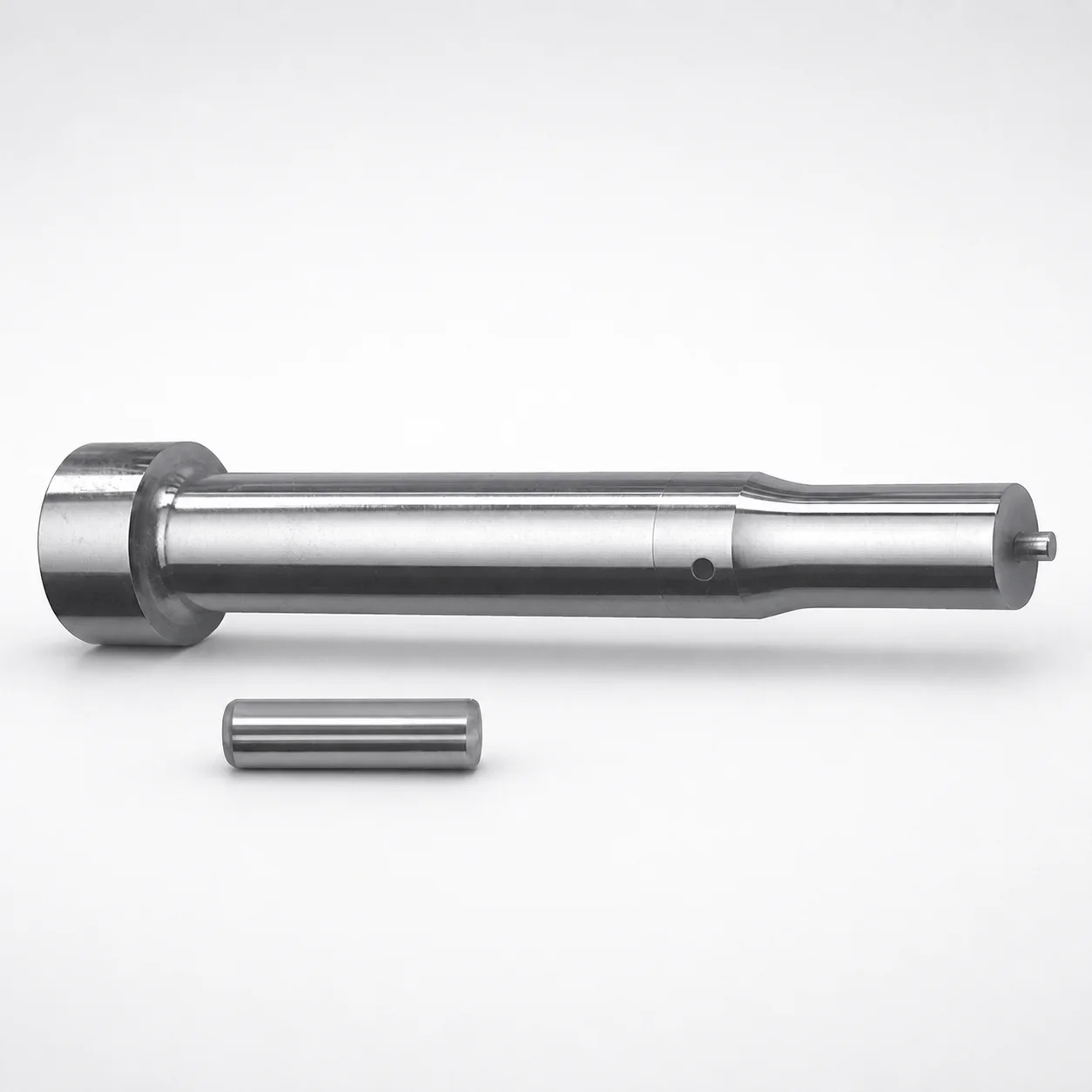
DAYTON XNAP Coating Center Dowel Punches for Heavy Load (Metric)
Center Dowel Punches for Heavy Load (DAYTON XNAP coating) are built for reliable location in heavy punch and die assemblies, supporting stable center alignment under repeated press cycles.
- Metric heavy-load center dowel punch body for accurate locating in tooling stacks
- XNAP coating helps improve surface wear resistance during operation
- Optimized tip geometry options (X, R, K, O, H, L, J, N, V, Y, Z) for matching workholding needs
- Suitable for press components that require consistent alignment and repeatable positioning
Specifications
112 configurations available
| Tip shape | D (Shank diameter) (mm) | Jektole group | L1 (Point Length) (mm) | L (Length) (mm) | P Dimension (mm) | W Dimension (mm) | R Dimension (mm) |
|---|---|---|---|---|---|---|---|
| H | 10 | J6M | 13 ~ 19 | 80 ~ 130 | 4 ~ 4.99 | 4 ~ 4.99 | - |
| H | 10 | J6M | 13 ~ 19 | 80 ~ 130 | 4 ~ 4.99 | 5 ~ 10 | - |
| H | 10 | J6M | 13 ~ 19 | 80 ~ 130 | 5 ~ 10 | 4 ~ 4.99 | - |
| H | 10 | J6M | 13 ~ 19 | 80 ~ 130 | 5 ~ 10 | 5 ~ 10 | - |
| H | 13 | J6M | 13 ~ 19 | 80 ~ 130 | 4 ~ 5.99 | 4 ~ 5.99 | - |
| H | 13 | J6M | 13 ~ 19 | 80 ~ 130 | 4 ~ 5.99 | 6 ~ 13 | - |
| H | 13 | J6M | 13 ~ 19 | 80 ~ 130 | 6 ~ 13 | 4 ~ 5.99 | - |
| H | 13 | J6M | 13 ~ 19 | 80 ~ 130 | 6 ~ 13 | 6 ~ 13 | - |
| H | 16 | J9M | 19 ~ 25 | 80 ~ 130 | 6 ~ 16 | 6 ~ 16 | - |
| H | 20 | J9M | 19 ~ 25 | 80 ~ 130 | 6 ~ 20 | 6 ~ 20 | - |
| H | 25 | J9M | 19 ~ 25 | 80 ~ 130 | 6 ~ 25 | 6 ~ 25 | - |
| J | 10 | J6M | 13 ~ 19 | 80 ~ 130 | 4 ~ 4.99 | 4 ~ 4.99 | - |
| J | 10 | J6M | 13 ~ 19 | 80 ~ 130 | 4 ~ 4.99 | 5 ~ 10 | - |
| J | 10 | J6M | 13 ~ 19 | 80 ~ 130 | 5 ~ 10 | 4 ~ 4.99 | - |
| J | 10 | J6M | 13 ~ 19 | 80 ~ 130 | 5 ~ 10 | 5 ~ 10 | - |
| J | 13 | J6M | 13 ~ 19 | 80 ~ 130 | 4 ~ 5.99 | 4 ~ 5.99 | - |
| J | 13 | J6M | 13 ~ 19 | 80 ~ 130 | 4 ~ 5.99 | 6 ~ 13 | - |
| J | 13 | J6M | 13 ~ 19 | 80 ~ 130 | 6 ~ 13 | 4 ~ 5.99 | - |
| J | 13 | J6M | 13 ~ 19 | 80 ~ 130 | 6 ~ 13 | 6 ~ 13 | - |
| J | 16 | J9M | 19 ~ 25 | 80 ~ 130 | 6 ~ 16 | 6 ~ 16 | - |
| J | 20 | J9M | 19 ~ 25 | 80 ~ 130 | 6 ~ 20 | 6 ~ 20 | - |
| J | 25 | J9M | 19 ~ 25 | 80 ~ 130 | 6 ~ 25 | 6 ~ 25 | - |
| K | 10 | J6M | 13 ~ 19 | 80 ~ 130 | 4 ~ 4.99 | 4 ~ 4.99 | 0.2 ~ 5 |
| K | 10 | J6M | 13 ~ 19 | 80 ~ 130 | 4 ~ 4.99 | 5 ~ 10 | 0.2 ~ 5 |
| K | 10 | J6M | 13 ~ 19 | 80 ~ 130 | 5 ~ 10 | 4 ~ 4.99 | 0.2 ~ 5 |
| K | 10 | J6M | 13 ~ 19 | 80 ~ 130 | 5 ~ 10 | 5 ~ 10 | 0.2 ~ 5 |
| K | 13 | J6M | 13 ~ 19 | 80 ~ 130 | 4 ~ 5.99 | 4 ~ 5.99 | 0.2 ~ 6.5 |
| K | 13 | J6M | 13 ~ 19 | 80 ~ 130 | 4 ~ 5.99 | 6 ~ 13 | 0.2 ~ 6.5 |
| K | 13 | J6M | 13 ~ 19 | 80 ~ 130 | 6 ~ 13 | 4 ~ 5.99 | 0.2 ~ 6.5 |
| K | 13 | J6M | 13 ~ 19 | 80 ~ 130 | 6 ~ 13 | 6 ~ 13 | 0.2 ~ 6.5 |
| K | 16 | J9M | 19 ~ 25 | 80 ~ 130 | 6 ~ 16 | 6 ~ 16 | 0.2 ~ 8 |
| K | 20 | J9M | 19 ~ 25 | 80 ~ 130 | 6 ~ 20 | 6 ~ 20 | 0.2 ~ 10 |
| K | 25 | J9M | 19 ~ 25 | 80 ~ 130 | 6 ~ 25 | 6 ~ 25 | 0.2 ~ 12.5 |
| L | 10 | J6M | 13 ~ 19 | 80 ~ 130 | 4 ~ 4.99 | 4 ~ 4.99 | - |
| L | 10 | J6M | 13 ~ 19 | 80 ~ 130 | 4 ~ 4.99 | 5 ~ 10 | - |
| L | 10 | J6M | 13 ~ 19 | 80 ~ 130 | 5 ~ 10 | 4 ~ 4.99 | - |
| L | 10 | J6M | 13 ~ 19 | 80 ~ 130 | 5 ~ 10 | 5 ~ 10 | - |
| L | 13 | J6M | 13 ~ 19 | 80 ~ 130 | 4 ~ 5.99 | 4 ~ 5.99 | - |
| L | 13 | J6M | 13 ~ 19 | 80 ~ 130 | 4 ~ 5.99 | 6 ~ 13 | - |
| L | 13 | J6M | 13 ~ 19 | 80 ~ 130 | 6 ~ 13 | 4 ~ 5.99 | - |
| L | 13 | J6M | 13 ~ 19 | 80 ~ 130 | 6 ~ 13 | 6 ~ 13 | - |
| L | 16 | J9M | 19 ~ 25 | 80 ~ 130 | 6 ~ 16 | 6 ~ 16 | - |
| L | 20 | J9M | 19 ~ 25 | 80 ~ 130 | 6 ~ 20 | 6 ~ 20 | - |
| L | 25 | J9M | 19 ~ 25 | 80 ~ 130 | 6 ~ 25 | 6 ~ 25 | - |
| N | 10 | J6M | 13 ~ 19 | 80 ~ 130 | - | 4 ~ 4.99 | - |
| N | 10 | J6M | 13 ~ 19 | 80 ~ 130 | - | 5 ~ 10 | - |
| N | 13 | J6M | 13 ~ 19 | 80 ~ 130 | - | 4 ~ 5.99 | - |
| N | 13 | J6M | 13 ~ 19 | 80 ~ 130 | - | 6 ~ 13 | - |
| N | 16 | J9M | 19 ~ 25 | 80 ~ 130 | - | 6 ~ 16 | - |
| N | 20 | J9M | 19 ~ 25 | 80 ~ 130 | - | 6 ~ 20 | - |
Product Guide
Application Scenarios+
Center dowel punches are used in injection mold tooling wherever precise, repeatable center alignment is critical during repeated press or clamp cycles. In heavy-duty punch and die assemblies, these metric punches help maintain stable stack-up location, reducing drift that can affect form accuracy and downstream part features.
- Automotive connector and bracket tooling: Pair with matching components in robust press stations to keep punch centering consistent through high-cycle production; the XNAP coating variant improves surface wear behavior at the locating interface.
- Electronics and appliance housings: Use in sub-assemblies where alignment between upper punch tooling and lower die is essential; the available tip shape options (H, J, K, L, N, O, R, V, X, Y, Z) allow geometry matching to your workholding stack.
- Progressive forming or heavy load cut & blank operations: Select the appropriate shank diameter and point length ranges to maintain guidance during rapid indexing; the fixed body length supports consistent engagement across a range of mold component heights.
Material & Process Details+
The provided product specifications describe a DAYTON XNAP coating center dowel punch, focused on improved wear resistance at the locating surface. While the underlying steel grade and hardness (HRC) are not specified in the available data, the coating is selected to enhance tribological performance under repeated contact and micro-sliding during press cycles.
- XNAP coating: Designed to reduce wear at the dowel/punch guidance interface, helping maintain dimensional stability for long runs.
- Tip geometry: Multiple tip shape options (H, J, K, L, N, O, R, V, X, Y, Z) support fit and guidance depending on the mating component profile.
For applications where higher substrate toughness is required, engineers typically compare base steel toughness vs. wear-focused surface treatments; however, this SKU’s specific heat treatment state and substrate grade are not listed here.
Sizing & Selection Guide+
Select dimensions by matching the punch’s engagement features to the mating tooling (guide bush, support plate, or corresponding locating hole/slot). Start with the shank diameter D in the available metric options: 10, 13, 16, 20, 25 mm. Use this to ensure correct clearance/fit and prevent locating play.
- Point length (L1): Choose from 13–19 mm or 19–25 mm to match the required penetration depth for guidance without over-travel.
- Body length (L): This is fixed as a range 80–130 mm; pick the value that aligns with your stack-up height so the working guidance portion is engaged under load.
- Geometry fit: Verify tip shape (H, J, K, L, N, O, R, V, X, Y, Z) and the P and W dimensions (P: 4–18 mm, W: 4–6 mm) so the mating profile matches.
- Radius (R): Select the correct R range (0.2–5, 0.2–6.5, 0.2–8, 0.2–10, 0.2–12.5 mm) to control contact area and reduce stress concentration.
Specify mating tolerances in your drawing notes, as the data provided lists dimensional ranges rather than specific tolerance grades.
Frequently Asked Questions
Which D shank diameter options are available for this heavy-load center dowel punch, and how do I choose the right one?+
For this metric center dowel punch, the shank diameter D is available in 10, 13, 16, 20, and 25 mm. Select the diameter that matches the corresponding locating feature in your punch tooling stack to avoid excessive clearance (misalignment) or interference (binding). If you’re reusing an existing guide layout, keep the same D to maintain the original alignment behavior.
How do L1 point length and the fixed L body length range (80–130 mm) affect engagement in punch tooling?+
The point length L1 is offered in two ranges: 13–19 mm and 19–25 mm, which determines how much the guiding portion enters the mating interface. The body length L is specified as 80–130 mm to suit different tool stack heights. Choose L1 to ensure stable guidance under press load while selecting L to keep the punch correctly positioned through the full cycle.
What tip shapes (H, J, K, L, N, O, R, V, X, Y, Z) should be selected for compatibility with different workholding profiles?+
This series provides multiple tip shape options: H, J, K, L, N, O, R, V, X, Y, Z. Use the tip shape that matches the mating profile in your locating system so the punch contacts the intended surfaces. When upgrading or swapping components, confirm the mating geometry first to prevent changes in contact points that can increase wear or introduce play.
How do the P and W dimensions (P: 4–18 mm, W: 4–6 mm) influence the fit with the mating tooling?+
The P dimension is specified as 4–18 mm and W as 4–6 mm. These dimensions are typically involved in how the locating feature interfaces with the mating part, so they must be consistent with your designed clearance/engagement. For best results, select the exact P and W values that correspond to your existing workholding profile.
What is the role of the XNAP coating in heavy-load punch tool life, and what substrate details are available?+
The data provided states that this series uses XNAP coating to improve surface wear resistance at the locating interface during operation. However, the underlying substrate steel grade, heat treatment state, and hardness (HRC) are not specified in the available specifications. When writing technical acceptance criteria, request substrate and coating thickness/coverage details from the supplier if your process requires them for certification.
Related Products

Metric Dowel Punches for Heavy Load with Single-Stepped Shank (M5)

Metric Center Dowel Punches for Heavy Load TiCN Coated

JIS Standard SKH51 Steel Ejector Punches for Heavy Load with Dowel Holes

SKH51 Steel TiCN Coating Ejector Punches for Heavy Load with Dowel Holes

RW Coated Dowel Punches for Heavy Load - Single-Stepped Shank

Center Dowel Ejector Punches for Heavy Load (RW Coating) - SKH51 Steel
Need Custom Specifications?
Our engineering team can help with custom configurations, material selection, and volume pricing.