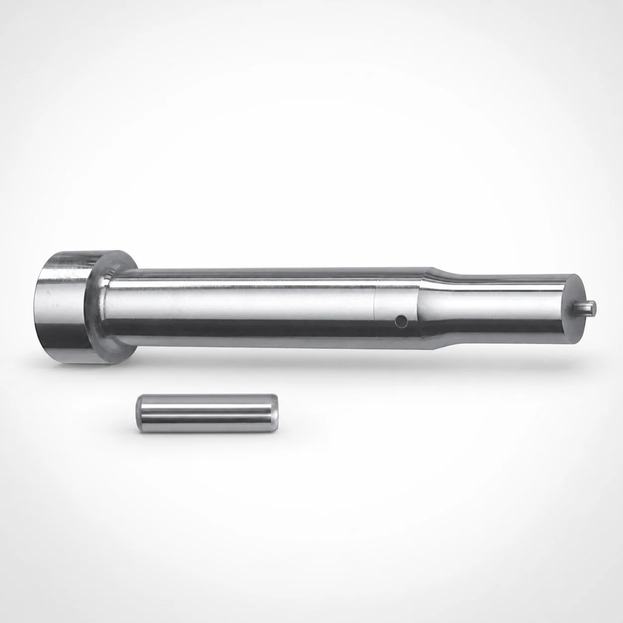
Center Dowel Punches for Heavy Load - Metric, XN DayTride® Coating
Center Dowel Punches for Heavy Load - Metric, XN DayTride® Coating are designed to locate hardened mold components and support heavy-duty ejector systems with controlled wear and consistent engagement. The metric center dowel punch form helps maintain alignment during repeated press cycles.
- Heavy-load center guiding for stable positioning in mold assemblies
- XN DayTride® coating helps improve surface durability under use
- Metric geometry supports repeatable fit and reliable ejector alignment
- Built for precision mold components requiring robust center pin locating
Specifications
112 configurations available
| Tip shape | D (Shank diameter) (mm) | Jektole group | L1 (Point Length) (mm) | L (Length) (mm) | P Dimension (mm) | W Dimension (mm) | R Dimension (mm) |
|---|---|---|---|---|---|---|---|
| H | 10 | J6M | 13 ~ 19 | 80 ~ 130 | 4 ~ 4.99 | 4 ~ 4.99 | - |
| H | 10 | J6M | 13 ~ 19 | 80 ~ 130 | 4 ~ 4.99 | 5 ~ 10 | - |
| H | 10 | J6M | 13 ~ 19 | 80 ~ 130 | 5 ~ 10 | 4 ~ 4.99 | - |
| H | 10 | J6M | 13 ~ 19 | 80 ~ 130 | 5 ~ 10 | 5 ~ 10 | - |
| H | 13 | J6M | 13 ~ 19 | 80 ~ 130 | 4 ~ 5.99 | 4 ~ 5.99 | - |
| H | 13 | J6M | 13 ~ 19 | 80 ~ 130 | 4 ~ 5.99 | 6 ~ 13 | - |
| H | 13 | J6M | 13 ~ 19 | 80 ~ 130 | 6 ~ 13 | 4 ~ 5.99 | - |
| H | 13 | J6M | 13 ~ 19 | 80 ~ 130 | 6 ~ 13 | 6 ~ 13 | - |
| H | 16 | J9M | 19 ~ 25 | 80 ~ 130 | 6 ~ 16 | 6 ~ 16 | - |
| H | 20 | J9M | 19 ~ 25 | 80 ~ 130 | 6 ~ 20 | 6 ~ 20 | - |
| H | 25 | J9M | 19 ~ 25 | 80 ~ 130 | 6 ~ 25 | 6 ~ 25 | - |
| J | 10 | J6M | 13 ~ 19 | 80 ~ 130 | 4 ~ 4.99 | 4 ~ 4.99 | - |
| J | 10 | J6M | 13 ~ 19 | 80 ~ 130 | 4 ~ 4.99 | 5 ~ 10 | - |
| J | 10 | J6M | 13 ~ 19 | 80 ~ 130 | 5 ~ 10 | 4 ~ 4.99 | - |
| J | 10 | J6M | 13 ~ 19 | 80 ~ 130 | 5 ~ 10 | 5 ~ 10 | - |
| J | 13 | J6M | 13 ~ 19 | 80 ~ 130 | 4 ~ 5.99 | 4 ~ 5.99 | - |
| J | 13 | J6M | 13 ~ 19 | 80 ~ 130 | 4 ~ 5.99 | 6 ~ 13 | - |
| J | 13 | J6M | 13 ~ 19 | 80 ~ 130 | 6 ~ 13 | 4 ~ 5.99 | - |
| J | 13 | J6M | 13 ~ 19 | 80 ~ 130 | 6 ~ 13 | 6 ~ 13 | - |
| J | 16 | J9M | 19 ~ 25 | 80 ~ 130 | 6 ~ 16 | 6 ~ 16 | - |
| J | 20 | J9M | 19 ~ 25 | 80 ~ 130 | 6 ~ 20 | 6 ~ 20 | - |
| J | 25 | J9M | 19 ~ 25 | 80 ~ 130 | 6 ~ 25 | 6 ~ 25 | - |
| K | 10 | J6M | 13 ~ 19 | 80 ~ 130 | 4 ~ 4.99 | 4 ~ 4.99 | 0.2 ~ 5 |
| K | 10 | J6M | 13 ~ 19 | 80 ~ 130 | 4 ~ 4.99 | 5 ~ 10 | 0.2 ~ 5 |
| K | 10 | J6M | 13 ~ 19 | 80 ~ 130 | 5 ~ 10 | 4 ~ 4.99 | 0.2 ~ 5 |
| K | 10 | J6M | 13 ~ 19 | 80 ~ 130 | 5 ~ 10 | 5 ~ 10 | 0.2 ~ 5 |
| K | 13 | J6M | 13 ~ 19 | 80 ~ 130 | 4 ~ 5.99 | 4 ~ 5.99 | 0.2 ~ 6.5 |
| K | 13 | J6M | 13 ~ 19 | 80 ~ 130 | 4 ~ 5.99 | 6 ~ 13 | 0.2 ~ 6.5 |
| K | 13 | J6M | 13 ~ 19 | 80 ~ 130 | 6 ~ 13 | 4 ~ 5.99 | 0.2 ~ 6.5 |
| K | 13 | J6M | 13 ~ 19 | 80 ~ 130 | 6 ~ 13 | 6 ~ 13 | 0.2 ~ 6.5 |
| K | 16 | J9M | 19 ~ 25 | 80 ~ 130 | 6 ~ 16 | 6 ~ 16 | 0.2 ~ 8 |
| K | 20 | J9M | 19 ~ 25 | 80 ~ 130 | 6 ~ 20 | 6 ~ 20 | 0.2 ~ 10 |
| K | 25 | J9M | 19 ~ 25 | 80 ~ 130 | 6 ~ 25 | 6 ~ 25 | 0.2 ~ 12.5 |
| L | 10 | J6M | 13 ~ 19 | 80 ~ 130 | 4 ~ 4.99 | 4 ~ 4.99 | - |
| L | 10 | J6M | 13 ~ 19 | 80 ~ 130 | 4 ~ 4.99 | 5 ~ 10 | - |
| L | 10 | J6M | 13 ~ 19 | 80 ~ 130 | 5 ~ 10 | 4 ~ 4.99 | - |
| L | 10 | J6M | 13 ~ 19 | 80 ~ 130 | 5 ~ 10 | 5 ~ 10 | - |
| L | 13 | J6M | 13 ~ 19 | 80 ~ 130 | 4 ~ 5.99 | 4 ~ 5.99 | - |
| L | 13 | J6M | 13 ~ 19 | 80 ~ 130 | 4 ~ 5.99 | 6 ~ 13 | - |
| L | 13 | J6M | 13 ~ 19 | 80 ~ 130 | 6 ~ 13 | 4 ~ 5.99 | - |
| L | 13 | J6M | 13 ~ 19 | 80 ~ 130 | 6 ~ 13 | 6 ~ 13 | - |
| L | 16 | J9M | 19 ~ 25 | 80 ~ 130 | 6 ~ 16 | 6 ~ 16 | - |
| L | 20 | J9M | 19 ~ 25 | 80 ~ 130 | 6 ~ 20 | 6 ~ 20 | - |
| L | 25 | J9M | 19 ~ 25 | 80 ~ 130 | 6 ~ 25 | 6 ~ 25 | - |
| N | 10 | J6M | 13 ~ 19 | 80 ~ 130 | - | 4 ~ 4.99 | - |
| N | 10 | J6M | 13 ~ 19 | 80 ~ 130 | - | 5 ~ 10 | - |
| N | 13 | J6M | 13 ~ 19 | 80 ~ 130 | - | 4 ~ 5.99 | - |
| N | 13 | J6M | 13 ~ 19 | 80 ~ 130 | - | 6 ~ 13 | - |
| N | 16 | J9M | 19 ~ 25 | 80 ~ 130 | - | 6 ~ 16 | - |
| N | 20 | J9M | 19 ~ 25 | 80 ~ 130 | - | 6 ~ 20 | - |
Product Guide
Application Scenarios+
These heavy-load center dowel punches are used as primary locating members in injection mold tooling where the ejector system and tool halves must stay aligned through high cycles. In precision molds, they help maintain stable engagement during repeated press/return movements, reducing the risk of drift that can affect ejection performance and part dimensional control.
In automotive connector and sensor housing molds, the metric shank sizes and heavy-duty guidance support consistent pin-to-bushing alignment, which is critical when ejector forces are higher and cycle times are demanding. The XN DayTride® coating variant is suited to improve surface durability under sliding contact during ejection.
For industrial housings and large-format parts, the available point-length options (L1 = 13–19 mm or 19–25 mm) allow designers to tune insertion depth for reliable centering without excessive protrusion. Multiple tip shapes (H, J, K, L, N, O, R, V, X, Y, Z) also support compatibility with different mating features.
- Guides heavy-load ejector systems with controlled wear
- Metric geometry supports repeatable engagement
- Coated surface improves tool life in sliding/locating contact
Material & Process Details+
The provided configuration specifies the punch geometry and XN DayTride® coating, but does not list a base steel grade or hardness value. Because the steel grade, heat treatment state (e.g., quenched & tempered, pre-hardened, nitrided), and measured HRC are not included in the input data, hardness and toughness trade-offs cannot be confirmed for this exact SKU.
For engineering planning, treat the coating as the differentiator for wear behavior at the sliding locating interface. In heavy-load center guiding applications, coatings such as DayTride® are typically selected to enhance surface durability and reduce adhesive/abrasive wear during repeated cycles.
- Coating: XN DayTride® (improves surface durability under use)
- Material/heat treatment: not specified in provided data
- Hardness (HRC) & toughness: not provided; verify on request or drawing package
Sizing & Selection Guide+
Select the center dowel punch by matching the metric shank diameter (D), overall length (L = 80–130 mm), and point length (L1) to your mold core/cavity locating design. For heavy-load guiding, ensure the pin provides sufficient insertion length to maintain stable center alignment while avoiding interference with ejector components.
- D (mm): choose 10, 13, 16, 20, or 25 based on the required locating capacity and the mating bushing/plate bore.
- L1 (mm): select 13–19 mm or 19–25 mm to control the depth of the locating point.
- L (mm): use the fixed overall length range 80–130 mm to fit within the tool stack-up.
Geometric compatibility is also driven by tip shape (H, J, K, L, N, O, R, V, X, Y, Z) and the P (4–18 mm) / W (4–6 mm) / R (0.2–5, 0.2–6.5, 0.2–8, 0.2–10, 0.2–12.5 mm) dimensions. Use P/W/R to match the mating feature profile. Tolerance guidance is not provided in the input data—confirm pin-to-bushing fit tolerances with your supplier drawing or standards.
Frequently Asked Questions
Which shank diameter (D) options are available for this metric heavy-load center dowel punch, and how do I pick the right one?+
What point length (L1) should I use to balance alignment reliability with space constraints?+
How do the variable P, W, and R dimensions affect compatibility with the mating locating features?+
What is the meaning of the Jektole group (J6M, J9M) for mold design selection?+
Why choose the XN DayTride® coating variant for heavy-load center guiding?+
Related Products

Metric Dowel Punches for Heavy Load with Single-Stepped Shank (M5)

Metric Center Dowel Punches for Heavy Load TiCN Coated

JIS Standard SKH51 Steel Ejector Punches for Heavy Load with Dowel Holes

SKH51 Steel TiCN Coating Ejector Punches for Heavy Load with Dowel Holes

RW Coated Dowel Punches for Heavy Load - Single-Stepped Shank

Center Dowel Ejector Punches for Heavy Load (RW Coating) - SKH51 Steel
Need Custom Specifications?
Our engineering team can help with custom configurations, material selection, and volume pricing.