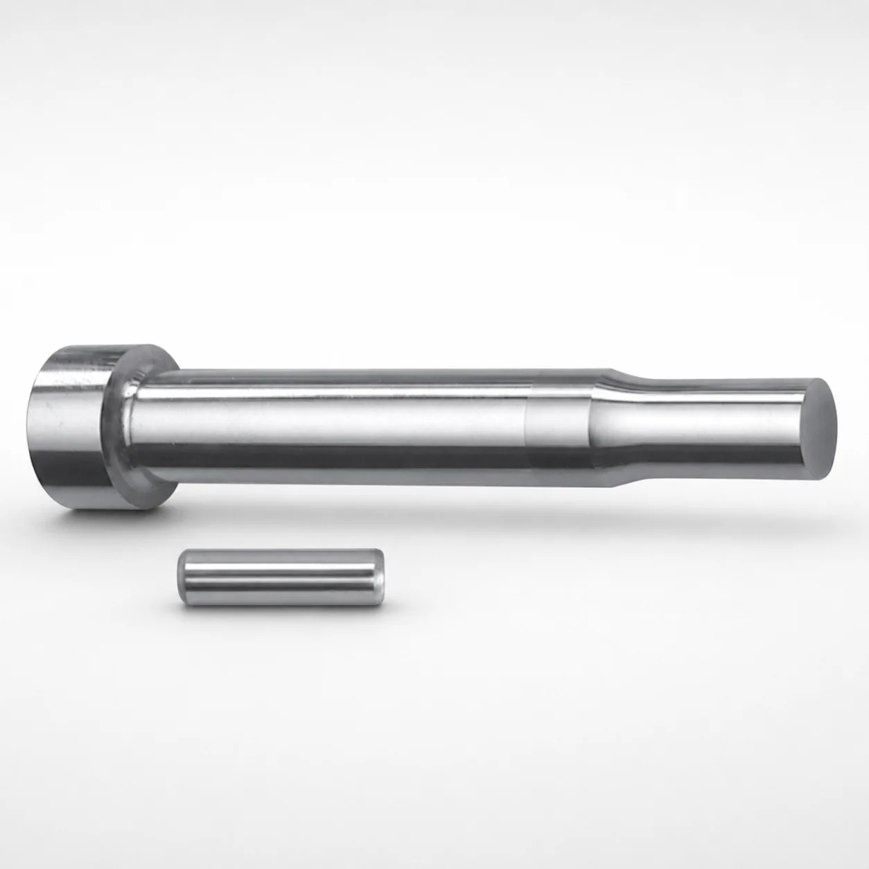
DAYTON XCN Coated Center Dowel Punches for Heavy Load - Metric
Center Dowel Punches for Heavy Load - Metric are designed for stable centering and reliable forming in heavy-duty die setups. The XCN coating supports improved wear resistance while maintaining dependable punch performance during repeated cycles.
- Heavy-load centering design helps stabilize dowel hole positioning
- XCN coating improves abrasion resistance for long production runs
- Metric configuration supports repeatable assembly alignment in tooling
- Suitable for die alignment operations where punch stability matters
Specifications
164 configurations available
| Tip shape | D (Shank diameter) (mm) | L1 (Point Length) (mm) | L (Length) (mm) | P Dimension (mm) | W Dimension (mm) | R Dimension (mm) |
|---|---|---|---|---|---|---|
| H | 10 | 13 ~ 19 | 80 ~ 130 | 1.5 ~ 2.99 | 1.5 ~ 2.99 | - |
| H | 10 | 13 ~ 19 | 80 ~ 130 | 1.5 ~ 2.99 | 3 ~ 10 | - |
| H | 10 | 13 ~ 19 | 80 ~ 130 | 3 ~ 10 | 1.5 ~ 2.99 | - |
| H | 10 | 13 ~ 19 | 80 ~ 130 | 3 ~ 10 | 3 ~ 10 | - |
| H | 13 | 13 ~ 19 | 80 ~ 130 | 1.5 ~ 2.99 | 1.5 ~ 2.99 | - |
| H | 13 | 13 ~ 19 | 80 ~ 130 | 1.5 ~ 2.99 | 3 ~ 13 | - |
| H | 13 | 13 ~ 19 | 80 ~ 130 | 3 ~ 13 | 1.5 ~ 2.99 | - |
| H | 13 | 13 ~ 19 | 80 ~ 130 | 3 ~ 13 | 3 ~ 13 | - |
| H | 16 | 19 ~ 25 | 80 ~ 130 | 3 ~ 3.99 | 3 ~ 3.99 | - |
| H | 16 | 19 ~ 25 | 80 ~ 130 | 3 ~ 3.99 | 4 ~ 16 | - |
| H | 16 | 19 ~ 25 | 80 ~ 130 | 4 ~ 16 | 3 ~ 3.99 | - |
| H | 16 | 19 ~ 25 | 80 ~ 130 | 4 ~ 16 | 4 ~ 16 | - |
| H | 20 | 19 ~ 25 | 80 ~ 130 | 3 ~ 4.99 | 3 ~ 4.99 | - |
| H | 20 | 19 ~ 25 | 80 ~ 130 | 3 ~ 4.99 | 5 ~ 20 | - |
| H | 20 | 19 ~ 25 | 80 ~ 130 | 5 ~ 20 | 3 ~ 4.99 | - |
| H | 20 | 19 ~ 25 | 80 ~ 130 | 5 ~ 20 | 5 ~ 20 | - |
| H | 25 | 19 ~ 25 | 80 ~ 130 | 6 ~ 25 | 6 ~ 25 | - |
| J | 10 | 13 ~ 19 | 80 ~ 130 | 1.5 ~ 2.99 | 1.5 ~ 2.99 | - |
| J | 10 | 13 ~ 19 | 80 ~ 130 | 1.5 ~ 2.99 | 3 ~ 10 | - |
| J | 10 | 13 ~ 19 | 80 ~ 130 | 3 ~ 10 | 1.5 ~ 2.99 | - |
| J | 10 | 13 ~ 19 | 80 ~ 130 | 3 ~ 10 | 3 ~ 10 | - |
| J | 13 | 13 ~ 19 | 80 ~ 130 | 1.5 ~ 2.99 | 1.5 ~ 2.99 | - |
| J | 13 | 13 ~ 19 | 80 ~ 130 | 1.5 ~ 2.99 | 3 ~ 13 | - |
| J | 13 | 13 ~ 19 | 80 ~ 130 | 3 ~ 13 | 1.5 ~ 2.99 | - |
| J | 13 | 13 ~ 19 | 80 ~ 130 | 3 ~ 13 | 3 ~ 13 | - |
| J | 16 | 19 ~ 25 | 80 ~ 130 | 3 ~ 3.99 | 3 ~ 3.99 | - |
| J | 16 | 19 ~ 25 | 80 ~ 130 | 3 ~ 3.99 | 4 ~ 16 | - |
| J | 16 | 19 ~ 25 | 80 ~ 130 | 4 ~ 16 | 3 ~ 3.99 | - |
| J | 16 | 19 ~ 25 | 80 ~ 130 | 4 ~ 16 | 4 ~ 16 | - |
| J | 20 | 19 ~ 25 | 80 ~ 130 | 3 ~ 4.99 | 3 ~ 4.99 | - |
| J | 20 | 19 ~ 25 | 80 ~ 130 | 3 ~ 4.99 | 5 ~ 20 | - |
| J | 20 | 19 ~ 25 | 80 ~ 130 | 5 ~ 20 | 3 ~ 4.99 | - |
| J | 20 | 19 ~ 25 | 80 ~ 130 | 5 ~ 20 | 5 ~ 20 | - |
| J | 25 | 19 ~ 25 | 80 ~ 130 | 6 ~ 25 | 6 ~ 25 | - |
| K | 10 | 13 ~ 19 | 80 ~ 130 | 1.5 ~ 2.99 | 1.5 ~ 2.99 | 0.2 ~ 5 |
| K | 10 | 13 ~ 19 | 80 ~ 130 | 1.5 ~ 2.99 | 3 ~ 10 | 0.2 ~ 5 |
| K | 10 | 13 ~ 19 | 80 ~ 130 | 3 ~ 10 | 1.5 ~ 2.99 | 0.2 ~ 5 |
| K | 10 | 13 ~ 19 | 80 ~ 130 | 3 ~ 10 | 3 ~ 10 | 0.2 ~ 5 |
| K | 13 | 13 ~ 19 | 80 ~ 130 | 1.5 ~ 2.99 | 1.5 ~ 2.99 | 0.2 ~ 6.5 |
| K | 13 | 13 ~ 19 | 80 ~ 130 | 1.5 ~ 2.99 | 3 ~ 13 | 0.2 ~ 6.5 |
| K | 13 | 13 ~ 19 | 80 ~ 130 | 3 ~ 13 | 1.5 ~ 2.99 | 0.2 ~ 6.5 |
| K | 13 | 13 ~ 19 | 80 ~ 130 | 3 ~ 13 | 3 ~ 13 | 0.2 ~ 6.5 |
| K | 16 | 19 ~ 25 | 80 ~ 130 | 3 ~ 3.99 | 3 ~ 3.99 | 0.2 ~ 8 |
| K | 16 | 19 ~ 25 | 80 ~ 130 | 3 ~ 3.99 | 4 ~ 16 | 0.2 ~ 8 |
| K | 16 | 19 ~ 25 | 80 ~ 130 | 4 ~ 16 | 3 ~ 3.99 | 0.2 ~ 8 |
| K | 16 | 19 ~ 25 | 80 ~ 130 | 4 ~ 16 | 4 ~ 16 | 0.2 ~ 8 |
| K | 20 | 19 ~ 25 | 80 ~ 130 | 3 ~ 4.99 | 3 ~ 4.99 | 0.2 ~ 10 |
| K | 20 | 19 ~ 25 | 80 ~ 130 | 3 ~ 4.99 | 5 ~ 20 | 0.2 ~ 10 |
| K | 20 | 19 ~ 25 | 80 ~ 130 | 5 ~ 20 | 3 ~ 4.99 | 0.2 ~ 10 |
| K | 20 | 19 ~ 25 | 80 ~ 130 | 5 ~ 20 | 5 ~ 20 | 0.2 ~ 10 |
Product Guide
Application Scenarios+
These heavy-load center dowel punches are used during precision injection mold and die build-up to establish reliable dowel hole location before final assembly. In practice, they help form and maintain stable centering under repeated clamp/return cycles, reducing the risk of progressive misalignment.
- Automotive connector and sensor housing tooling: the consistent shank diameter options (10, 13, 16, 20, 25 mm) and long body length (L = 80–130 mm) support accurate alignment for large, heavy components where wear and load can shift dowel features.
- High-cycle industrial housings: the XCN coating is selected to improve abrasion resistance for long production runs, helping the punch maintain dimensional stability when used repeatedly.
- Medical device housings (multi-part inserts): metric configuration supports repeatable assembly alignment, which is important when multiple cores/cavities must register consistently across maintenance intervals.
The heavy-load centering design plus abrasion-resistant XCN coating makes this variant suitable where alignment integrity and cycle durability are critical.
Material & Process Details+
The provided product data specifies an XCN-coated center dowel punch intended for improved abrasion resistance during heavy-duty use. However, the input does not list the base steel grade, specific heat-treatment state (e.g., quenched & tempered, nitrided), or the achievable HRC hardness range.
- XCN coating role: increases wear and abrasion resistance at the working surfaces that experience sliding/impact during hole-forming and alignment.
- Trade-offs: with coatings, performance depends on coating thickness/adhesion versus underlying toughness; the underlying steel must still support the heavy-load centering function.
Because the steel grade and hardness are not specified in the supplied metadata, engineers should confirm the material certification for base hardness and heat treatment requirements before final selection.
Sizing & Selection Guide+
Select dimensions by matching the punch geometry to the intended dowel feature in the mold components (plate/register locations, core/cavity alignment blocks, or heavy die setup plates).
- Shank diameter (D, mm): choose from D = 10, 13, 16, 20, or 25 to correspond to the target dowel bore size and guiding clearance requirements in your assembly.
- Overall length (L, mm): L is fixed in the range 80–130 mm; ensure the punch length provides the required reach through stacked tooling and still maintains full guidance during centering.
- Point length (L1, mm): select L1 = 13–19 or 19–25 to align with the depth of the hole-forming/spotting operation.
- Tip shape and fine geometry: select the tip shape (H, J, K, L, N, O, R, V, X, Y, Z) based on the dowel hole-forming profile, and match the P and W dimensions (P = 1.5–18 mm; W = 1.5–6 mm) and the R radius range (R = 0.2–5, 0.2–6.5, 0.2–8, 0.2–10, 0.2–12.5) to the desired edge radius.
If your drawing specifies fit/clearance, verify the punch’s D and tip-forming profile against the mold component tolerances to maintain repeatable registration.
Frequently Asked Questions
Which shank diameter (D) should I choose for dowel hole alignment in a heavy-load mold assembly?+
How do I select the correct length (L and L1) for stacked plates and the depth of the dowel locating feature?+
What tip shapes are available and how do they affect the dowel hole-forming profile?+
How does the XCN coating benefit repeated cycles in heavy-load die setups?+
How do P, W, and R dimensions relate to the radius and surface contact of the formed dowel feature?+
Related Products

Metric Dowel Punches for Heavy Load with Single-Stepped Shank (M5)

Metric Center Dowel Punches for Heavy Load TiCN Coated

JIS Standard SKH51 Steel Ejector Punches for Heavy Load with Dowel Holes

SKH51 Steel TiCN Coating Ejector Punches for Heavy Load with Dowel Holes

RW Coated Dowel Punches for Heavy Load - Single-Stepped Shank

Center Dowel Ejector Punches for Heavy Load (RW Coating) - SKH51 Steel
Need Custom Specifications?
Our engineering team can help with custom configurations, material selection, and volume pricing.