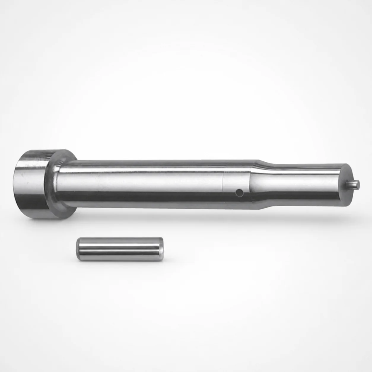
Center Dowel Punches for Heavy Load with XCN Coating
Center Dowel Punches for Heavy Load with XCN coating provide stable center positioning for heavy-duty die sets and assembly operations. The coating supports controlled wear resistance for repeatable performance in production.
- Center locating punch design for accurate alignment during heavy-load press work
- XCN coating helps improve surface durability under repeated cycles
- Designed for metric die and punch tool setups using available tip geometry options
- Suitable for die maintenance and tooling projects requiring dependable center guidance
Specifications
112 configurations available
| Tip shape | D (Shank diameter) (mm) | Jektole group | L1 (Point Length) (mm) | L (Length) (mm) | P Dimension (mm) | W Dimension (mm) | R Dimension (mm) |
|---|---|---|---|---|---|---|---|
| H | 10 | J6M | 13 ~ 19 | 80 ~ 130 | 4 ~ 4.99 | 4 ~ 4.99 | - |
| H | 10 | J6M | 13 ~ 19 | 80 ~ 130 | 4 ~ 4.99 | 5 ~ 10 | - |
| H | 10 | J6M | 13 ~ 19 | 80 ~ 130 | 5 ~ 10 | 4 ~ 4.99 | - |
| H | 10 | J6M | 13 ~ 19 | 80 ~ 130 | 5 ~ 10 | 5 ~ 10 | - |
| H | 13 | J6M | 13 ~ 19 | 80 ~ 130 | 4 ~ 5.99 | 4 ~ 5.99 | - |
| H | 13 | J6M | 13 ~ 19 | 80 ~ 130 | 4 ~ 5.99 | 6 ~ 13 | - |
| H | 13 | J6M | 13 ~ 19 | 80 ~ 130 | 6 ~ 13 | 4 ~ 5.99 | - |
| H | 13 | J6M | 13 ~ 19 | 80 ~ 130 | 6 ~ 13 | 6 ~ 13 | - |
| H | 16 | J9M | 19 ~ 25 | 80 ~ 130 | 6 ~ 16 | 6 ~ 16 | - |
| H | 20 | J9M | 19 ~ 25 | 80 ~ 130 | 6 ~ 20 | 6 ~ 20 | - |
| H | 25 | J9M | 19 ~ 25 | 80 ~ 130 | 6 ~ 25 | 6 ~ 25 | - |
| J | 10 | J6M | 13 ~ 19 | 80 ~ 130 | 4 ~ 4.99 | 4 ~ 4.99 | - |
| J | 10 | J6M | 13 ~ 19 | 80 ~ 130 | 4 ~ 4.99 | 5 ~ 10 | - |
| J | 10 | J6M | 13 ~ 19 | 80 ~ 130 | 5 ~ 10 | 4 ~ 4.99 | - |
| J | 10 | J6M | 13 ~ 19 | 80 ~ 130 | 5 ~ 10 | 5 ~ 10 | - |
| J | 13 | J6M | 13 ~ 19 | 80 ~ 130 | 4 ~ 5.99 | 4 ~ 5.99 | - |
| J | 13 | J6M | 13 ~ 19 | 80 ~ 130 | 4 ~ 5.99 | 6 ~ 13 | - |
| J | 13 | J6M | 13 ~ 19 | 80 ~ 130 | 6 ~ 13 | 4 ~ 5.99 | - |
| J | 13 | J6M | 13 ~ 19 | 80 ~ 130 | 6 ~ 13 | 6 ~ 13 | - |
| J | 16 | J9M | 19 ~ 25 | 80 ~ 130 | 6 ~ 16 | 6 ~ 16 | - |
| J | 20 | J9M | 19 ~ 25 | 80 ~ 130 | 6 ~ 20 | 6 ~ 20 | - |
| J | 25 | J9M | 19 ~ 25 | 80 ~ 130 | 6 ~ 25 | 6 ~ 25 | - |
| K | 10 | J6M | 13 ~ 19 | 80 ~ 130 | 4 ~ 4.99 | 4 ~ 4.99 | 0.2 ~ 5 |
| K | 10 | J6M | 13 ~ 19 | 80 ~ 130 | 4 ~ 4.99 | 5 ~ 10 | 0.2 ~ 5 |
| K | 10 | J6M | 13 ~ 19 | 80 ~ 130 | 5 ~ 10 | 4 ~ 4.99 | 0.2 ~ 5 |
| K | 10 | J6M | 13 ~ 19 | 80 ~ 130 | 5 ~ 10 | 5 ~ 10 | 0.2 ~ 5 |
| K | 13 | J6M | 13 ~ 19 | 80 ~ 130 | 4 ~ 5.99 | 4 ~ 5.99 | 0.2 ~ 6.5 |
| K | 13 | J6M | 13 ~ 19 | 80 ~ 130 | 4 ~ 5.99 | 6 ~ 13 | 0.2 ~ 6.5 |
| K | 13 | J6M | 13 ~ 19 | 80 ~ 130 | 6 ~ 13 | 4 ~ 5.99 | 0.2 ~ 6.5 |
| K | 13 | J6M | 13 ~ 19 | 80 ~ 130 | 6 ~ 13 | 6 ~ 13 | 0.2 ~ 6.5 |
| K | 16 | J9M | 19 ~ 25 | 80 ~ 130 | 6 ~ 16 | 6 ~ 16 | 0.2 ~ 8 |
| K | 20 | J9M | 19 ~ 25 | 80 ~ 130 | 6 ~ 20 | 6 ~ 20 | 0.2 ~ 10 |
| K | 25 | J9M | 19 ~ 25 | 80 ~ 130 | 6 ~ 25 | 6 ~ 25 | 0.2 ~ 12.5 |
| L | 10 | J6M | 13 ~ 19 | 80 ~ 130 | 4 ~ 4.99 | 4 ~ 4.99 | - |
| L | 10 | J6M | 13 ~ 19 | 80 ~ 130 | 4 ~ 4.99 | 5 ~ 10 | - |
| L | 10 | J6M | 13 ~ 19 | 80 ~ 130 | 5 ~ 10 | 4 ~ 4.99 | - |
| L | 10 | J6M | 13 ~ 19 | 80 ~ 130 | 5 ~ 10 | 5 ~ 10 | - |
| L | 13 | J6M | 13 ~ 19 | 80 ~ 130 | 4 ~ 5.99 | 4 ~ 5.99 | - |
| L | 13 | J6M | 13 ~ 19 | 80 ~ 130 | 4 ~ 5.99 | 6 ~ 13 | - |
| L | 13 | J6M | 13 ~ 19 | 80 ~ 130 | 6 ~ 13 | 4 ~ 5.99 | - |
| L | 13 | J6M | 13 ~ 19 | 80 ~ 130 | 6 ~ 13 | 6 ~ 13 | - |
| L | 16 | J9M | 19 ~ 25 | 80 ~ 130 | 6 ~ 16 | 6 ~ 16 | - |
| L | 20 | J9M | 19 ~ 25 | 80 ~ 130 | 6 ~ 20 | 6 ~ 20 | - |
| L | 25 | J9M | 19 ~ 25 | 80 ~ 130 | 6 ~ 25 | 6 ~ 25 | - |
| N | 10 | J6M | 13 ~ 19 | 80 ~ 130 | - | 4 ~ 4.99 | - |
| N | 10 | J6M | 13 ~ 19 | 80 ~ 130 | - | 5 ~ 10 | - |
| N | 13 | J6M | 13 ~ 19 | 80 ~ 130 | - | 4 ~ 5.99 | - |
| N | 13 | J6M | 13 ~ 19 | 80 ~ 130 | - | 6 ~ 13 | - |
| N | 16 | J9M | 19 ~ 25 | 80 ~ 130 | - | 6 ~ 16 | - |
| N | 20 | J9M | 19 ~ 25 | 80 ~ 130 | - | 6 ~ 20 | - |
Product Guide
Application Scenarios+
Center dowel punches are used in injection and stamping tooling to maintain repeatable center alignment between moving and stationary components. This heavy-load variant with an XCN coating is especially suited for die sets and large press-related operations where locating accuracy directly affects part geometry and downstream assembly.
- Automotive and industrial stamping die sets: Use the punch to positively locate die halves during high-cycle operations, helping reduce drift from repeated loads.
- Large injection mold build-outs for housings/connectors: Integrate as a center guidance element to improve register accuracy during cavity/core assembly and maintenance.
- Tooling repair and rework: Replace worn alignment components; the XCN coating is designed to support controlled wear over repeated cycles, supporting stable positioning.
The available shank diameters (D = 10, 13, 16, 20, 25 mm) and point length options (L1 = 13–19, 19–25 mm) allow engineers to match guidance reach and load-bearing geometry for heavy-duty die and mold tooling.
Material & Process Details+
The provided specification data identifies this part family as heavy-load center dowel punches with an XCN coating, intended to enhance surface durability under repeated locating cycles. However, no specific base steel grade or heat-treatment condition (e.g., quenched & tempered, nitrided, or pre-hardened) is listed in the input data, so hardness (HRC) and exact wear/toughness trade-offs cannot be stated for this exact SKU.
- XCN coating role: The coating is used to improve wear resistance at the guiding/point contact area, helping preserve alignment accuracy over production runs.
- Material selection note: When base-steel options are offered for similar dowel punches, engineers typically balance wear resistance (often achieved by harder surface treatments) against toughness (to resist chipping under shock loads).
For projects requiring quantified HRC and validated treatment details, request the steel grade and heat-treatment certificate for series 250301835031.
Sizing & Selection Guide+
Select the dowel punch dimensions by matching the locating shank diameter (D) and working point length (L1) to the mating guidance features in your die set or mold assembly.
- Choose D (shank diameter, mm): 10, 13, 16, 20, or 25. Use the same diameter as the corresponding hole/bore design to ensure proper fit and concentric guidance.
- Choose point length L1 (mm): 13–19 or 19–25. Ensure L1 provides sufficient engagement depth for stable center positioning without over-insertion that could interfere with tool stack height.
- Check overall length L (mm): Fixed range 80–130. Confirm the full punch length accommodates your tool thickness and avoids bottoming during clamping.
- Verify geometry parameters: Tip shape options H, J, K, L, N, O, R, V, X, Y, Z; and dimensions P (4–18), W (4–6), plus R (0.2–5, 0.2–6.5, 0.2–8, 0.2–10, 0.2–12.5) based on your required point contour.
If your design uses tight locating fits, confirm mating hole/bore tolerance and surface finish targets; the input data does not specify tolerance classes for this series.
Frequently Asked Questions
Which shank diameter (D) options are available for the center dowel punch series 250301835031?+
How do I choose the point length L1 for adequate engagement without interfering with tool stack height?+
What tip shapes are offered, and when should I select a different tip shape (H, J, K, etc.)?+
What is the function of the XCN coating for heavy-load die alignment applications?+
Are specific heat treatment and hardness (HRC) values provided for this series?+
Related Products

Metric Dowel Punches for Heavy Load with Single-Stepped Shank (M5)

Metric Center Dowel Punches for Heavy Load TiCN Coated

JIS Standard SKH51 Steel Ejector Punches for Heavy Load with Dowel Holes

SKH51 Steel TiCN Coating Ejector Punches for Heavy Load with Dowel Holes

RW Coated Dowel Punches for Heavy Load - Single-Stepped Shank

Center Dowel Ejector Punches for Heavy Load (RW Coating) - SKH51 Steel
Need Custom Specifications?
Our engineering team can help with custom configurations, material selection, and volume pricing.