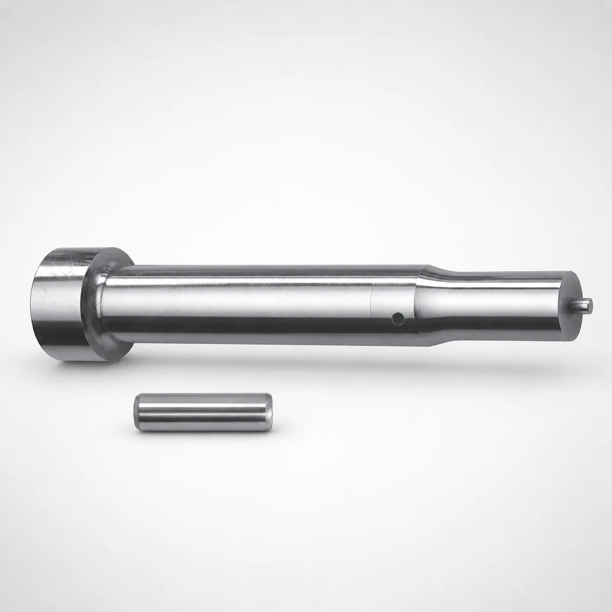
Center Dowel Punches for Heavy Load - Metric, XCD Coating
Center Dowel Punches for Heavy Load - Metric (XCD coating) from DAYTON are designed to deliver consistent center locating for die setups under demanding production loads, helping maintain alignment during repeated operations.
- Heavy-load center dowel punch construction supports reliable positioning in press and die applications.
- XCD coating improves surface wear resistance for longer service intervals in production.
- Metric shank options for fit across standard die components and tooling layouts.
- Available tip geometries (X, R, K, O, H, L, J, N, V, Y, Z) to match locating requirements.
Specifications
112 configurations available
| Tip shape | D (Shank diameter) (mm) | Jektole group | L1 (Point Length) (mm) | L (Length) (mm) | P Dimension (mm) | W Dimension (mm) | R Dimension (mm) |
|---|---|---|---|---|---|---|---|
| H | 10 | J6M | 13 ~ 19 | 80 ~ 130 | 4 ~ 4.99 | 4 ~ 4.99 | - |
| H | 10 | J6M | 13 ~ 19 | 80 ~ 130 | 4 ~ 4.99 | 5 ~ 10 | - |
| H | 10 | J6M | 13 ~ 19 | 80 ~ 130 | 5 ~ 10 | 4 ~ 4.99 | - |
| H | 10 | J6M | 13 ~ 19 | 80 ~ 130 | 5 ~ 10 | 5 ~ 10 | - |
| H | 13 | J6M | 13 ~ 19 | 80 ~ 130 | 4 ~ 5.99 | 4 ~ 5.99 | - |
| H | 13 | J6M | 13 ~ 19 | 80 ~ 130 | 4 ~ 5.99 | 6 ~ 13 | - |
| H | 13 | J6M | 13 ~ 19 | 80 ~ 130 | 6 ~ 13 | 4 ~ 5.99 | - |
| H | 13 | J6M | 13 ~ 19 | 80 ~ 130 | 6 ~ 13 | 6 ~ 13 | - |
| H | 16 | J9M | 19 ~ 25 | 80 ~ 130 | 6 ~ 16 | 6 ~ 16 | - |
| H | 20 | J9M | 19 ~ 25 | 80 ~ 130 | 6 ~ 20 | 6 ~ 20 | - |
| H | 25 | J9M | 19 ~ 25 | 80 ~ 130 | 6 ~ 25 | 6 ~ 25 | - |
| J | 10 | J6M | 13 ~ 19 | 80 ~ 130 | 4 ~ 4.99 | 4 ~ 4.99 | - |
| J | 10 | J6M | 13 ~ 19 | 80 ~ 130 | 4 ~ 4.99 | 5 ~ 10 | - |
| J | 10 | J6M | 13 ~ 19 | 80 ~ 130 | 5 ~ 10 | 4 ~ 4.99 | - |
| J | 10 | J6M | 13 ~ 19 | 80 ~ 130 | 5 ~ 10 | 5 ~ 10 | - |
| J | 13 | J6M | 13 ~ 19 | 80 ~ 130 | 4 ~ 5.99 | 4 ~ 5.99 | - |
| J | 13 | J6M | 13 ~ 19 | 80 ~ 130 | 4 ~ 5.99 | 6 ~ 13 | - |
| J | 13 | J6M | 13 ~ 19 | 80 ~ 130 | 6 ~ 13 | 4 ~ 5.99 | - |
| J | 13 | J6M | 13 ~ 19 | 80 ~ 130 | 6 ~ 13 | 6 ~ 13 | - |
| J | 16 | J9M | 19 ~ 25 | 80 ~ 130 | 6 ~ 16 | 6 ~ 16 | - |
| J | 20 | J9M | 19 ~ 25 | 80 ~ 130 | 6 ~ 20 | 6 ~ 20 | - |
| J | 25 | J9M | 19 ~ 25 | 80 ~ 130 | 6 ~ 25 | 6 ~ 25 | - |
| K | 10 | J6M | 13 ~ 19 | 80 ~ 130 | 4 ~ 4.99 | 4 ~ 4.99 | 0.2 ~ 5 |
| K | 10 | J6M | 13 ~ 19 | 80 ~ 130 | 4 ~ 4.99 | 5 ~ 10 | 0.2 ~ 5 |
| K | 10 | J6M | 13 ~ 19 | 80 ~ 130 | 5 ~ 10 | 4 ~ 4.99 | 0.2 ~ 5 |
| K | 10 | J6M | 13 ~ 19 | 80 ~ 130 | 5 ~ 10 | 5 ~ 10 | 0.2 ~ 5 |
| K | 13 | J6M | 13 ~ 19 | 80 ~ 130 | 4 ~ 5.99 | 4 ~ 5.99 | 0.2 ~ 6.5 |
| K | 13 | J6M | 13 ~ 19 | 80 ~ 130 | 4 ~ 5.99 | 6 ~ 13 | 0.2 ~ 6.5 |
| K | 13 | J6M | 13 ~ 19 | 80 ~ 130 | 6 ~ 13 | 4 ~ 5.99 | 0.2 ~ 6.5 |
| K | 13 | J6M | 13 ~ 19 | 80 ~ 130 | 6 ~ 13 | 6 ~ 13 | 0.2 ~ 6.5 |
| K | 16 | J9M | 19 ~ 25 | 80 ~ 130 | 6 ~ 16 | 6 ~ 16 | 0.2 ~ 8 |
| K | 20 | J9M | 19 ~ 25 | 80 ~ 130 | 6 ~ 20 | 6 ~ 20 | 0.2 ~ 10 |
| K | 25 | J9M | 19 ~ 25 | 80 ~ 130 | 6 ~ 25 | 6 ~ 25 | 0.2 ~ 12.5 |
| L | 10 | J6M | 13 ~ 19 | 80 ~ 130 | 4 ~ 4.99 | 4 ~ 4.99 | - |
| L | 10 | J6M | 13 ~ 19 | 80 ~ 130 | 4 ~ 4.99 | 5 ~ 10 | - |
| L | 10 | J6M | 13 ~ 19 | 80 ~ 130 | 5 ~ 10 | 4 ~ 4.99 | - |
| L | 10 | J6M | 13 ~ 19 | 80 ~ 130 | 5 ~ 10 | 5 ~ 10 | - |
| L | 13 | J6M | 13 ~ 19 | 80 ~ 130 | 4 ~ 5.99 | 4 ~ 5.99 | - |
| L | 13 | J6M | 13 ~ 19 | 80 ~ 130 | 4 ~ 5.99 | 6 ~ 13 | - |
| L | 13 | J6M | 13 ~ 19 | 80 ~ 130 | 6 ~ 13 | 4 ~ 5.99 | - |
| L | 13 | J6M | 13 ~ 19 | 80 ~ 130 | 6 ~ 13 | 6 ~ 13 | - |
| L | 16 | J9M | 19 ~ 25 | 80 ~ 130 | 6 ~ 16 | 6 ~ 16 | - |
| L | 20 | J9M | 19 ~ 25 | 80 ~ 130 | 6 ~ 20 | 6 ~ 20 | - |
| L | 25 | J9M | 19 ~ 25 | 80 ~ 130 | 6 ~ 25 | 6 ~ 25 | - |
| N | 10 | J6M | 13 ~ 19 | 80 ~ 130 | - | 4 ~ 4.99 | - |
| N | 10 | J6M | 13 ~ 19 | 80 ~ 130 | - | 5 ~ 10 | - |
| N | 13 | J6M | 13 ~ 19 | 80 ~ 130 | - | 4 ~ 5.99 | - |
| N | 13 | J6M | 13 ~ 19 | 80 ~ 130 | - | 6 ~ 13 | - |
| N | 16 | J9M | 19 ~ 25 | 80 ~ 130 | - | 6 ~ 16 | - |
| N | 20 | J9M | 19 ~ 25 | 80 ~ 130 | - | 6 ~ 20 | - |
Product Guide
Application Scenarios+
These heavy-load center dowel punches are used in injection mold tooling and progressive die line setups where repeatable center alignment is critical for each cycle. They guide punch-driven locating between die halves, tooling carriers, or press frames to reduce gradual misalignment caused by vibration and high press tonnage.
In automotive connector and terminal molds, the XCD-coated working surface helps resist fretting and wear on the locating point, supporting stable part-to-part positioning during high-volume runs. Tip geometry options (X, R, K, O, H, L, J, N, V, Y, Z) allow engineers to match the locating contact profile to their cavity/core lead-in and register hole features.
For medical device housing and insert molds, where tight cosmetic and dimensional consistency are required, the metric shank diameter range (10–25 mm) supports a secure guided fit in standard die layouts while the available point length windows (13–19 and 19–25 mm) help tune penetration depth without over-stressing the guide interface.
Material & Process Details+
The provided specification set for this series focuses on geometry and coating; no steel grade, heat treatment, or measured hardness is stated in the input data. For this reason, material hardness (HRC), quenched & tempered condition, nitriding, or other heat-treatment specifics cannot be claimed without sourcing the corresponding technical sheet.
What can be supported by the metadata is the XCD coating itself: it is intended to enhance wear resistance and maintain stable locating under production loads. In heavy-load alignment applications, this typically improves resistance to surface scuffing and reduces wear-driven positional drift.
- Coating impact: Prioritizes wear life at the locating interface, helping preserve repeatability over more cycles.
- Trade-off: Coatings are most beneficial for wear-dominant regimes; if impact/bending becomes dominant, base material toughness and fit quality become more critical than coating alone.
Sizing & Selection Guide+
Select the dowel punch dimensions to match the locating/register geometry of the mating die halves while controlling penetration depth and side loading.
1) Shank diameter (D): Choose from the specified metric range D = 10, 13, 16, 20, or 25 mm to fit the corresponding die guide bore/hole diameter used in your tooling layout.
2) Point length (L1): Use either L1 = 13–19 mm or L1 = 19–25 mm based on how far the locating point must engage into the mating feature for repeatable center reference without excessive travel.
3) Overall body length (L): Confirm your tooling envelope against the fixed range L = 80–130 mm.
- 4) Tip profile (shape): Match the selected contact geometry (H, J, K, L, N, O, R, V, X, Y, Z) to the register feature shape so alignment is repeatable across cycles.
- 5) Additional dimensions: Verify P = 4–18 mm, W = 4–6 mm, and the specified R ranges (0.2–5 up to 0.2–12.5 mm) correspond to your mating lead-in radii and contact pattern.
For best stability, ensure the chosen D and tip engagement meet your assembly tolerances; even with wear-resistant coating, excessive clearance can increase register variation.
Frequently Asked Questions
Which tip shapes (H/J/K/L/N/O/R/V/X/Y/Z) are used to tune centering contact in heavy-load die alignment?+
This series is available with variable tip geometry including H, J, K, L, N, O, R, V, X, Y, and Z. Select the profile that matches the mating locating feature so the center reference is established consistently during press cycles. Using the wrong tip geometry can shift the contact pattern and increase alignment variation under load.
How do I choose the correct shank diameter D for my die guide bore?+
Choose the metric D from 10, 13, 16, 20, or 25 mm to match the mating guide hole diameter in your tooling layout. This ensures a guided fit that supports stable center locating during repeated operations. After selection, confirm that assembly clearances within your die set tolerances are compatible with the expected thermal expansion and wear allowance.
What point length L1 options (13–19 mm or 19–25 mm) should be used to avoid insufficient engagement?+
The product supports L1 = 13–19 mm or L1 = 19–25 mm. Use the shorter range when your register engagement depth is limited by die geometry, and the longer range when deeper engagement is required to establish a stable center reference. Verify in your assembly that L1 does not cause over-penetration or excessive force concentration on the mating feature.
What does the XCD coating do for heavy-load production alignment?+
The series includes XCD coating, specified to improve wear resistance and help maintain stable alignment during demanding production loads. In die and press environments, locating interfaces can suffer fretting and surface degradation that leads to positional drift. The coating is intended to extend service intervals by reducing wear at the working surface.
How do I validate compatibility of P, W, and R dimensions with the mating register feature?+
Check the specified P dimension range 4–18 mm and W range 4–6 mm, then verify the locating contact radius R falls within the provided ranges (e.g., 0.2–5, 0.2–6.5, 0.2–8, 0.2–10, or 0.2–12.5 depending on the configuration). Matching these geometry constraints helps ensure the punch seats correctly and reproduces the intended center alignment profile.
Related Products

Metric Dowel Punches for Heavy Load with Single-Stepped Shank (M5)

Metric Center Dowel Punches for Heavy Load TiCN Coated

JIS Standard SKH51 Steel Ejector Punches for Heavy Load with Dowel Holes

SKH51 Steel TiCN Coating Ejector Punches for Heavy Load with Dowel Holes

RW Coated Dowel Punches for Heavy Load - Single-Stepped Shank

Center Dowel Ejector Punches for Heavy Load (RW Coating) - SKH51 Steel
Need Custom Specifications?
Our engineering team can help with custom configurations, material selection, and volume pricing.