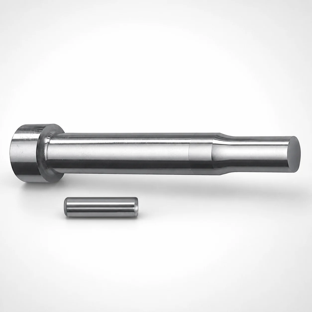
Center Dowel Punches for Heavy Load Metric
Center Dowel Punches for Heavy Load Metric by DAYTON provide stable die positioning for repetitive molding operations, improving repeatability under high load. The metric center layout supports accurate alignment in heavy-duty tool sets.
- Center locating function for consistent alignment during die setup
- Metric design supports repeatable, heavy-load die positioning
- Tip shape options for controlled contact and guidance
- Use DAYTON LAMINA standardized part numbers for easier identification
Specifications
164 configurations available
| Tip shape | D (Shank diameter) (mm) | L1 (Point Length) (mm) | L (Length) (mm) | P Dimension (mm) | W Dimension (mm) | R Dimension (mm) |
|---|---|---|---|---|---|---|
| H | 10 | 13 ~ 19 | 80 ~ 130 | 1.5 ~ 2.99 | 1.5 ~ 2.99 | - |
| H | 10 | 13 ~ 19 | 80 ~ 130 | 1.5 ~ 2.99 | 3 ~ 10 | - |
| H | 10 | 13 ~ 19 | 80 ~ 130 | 3 ~ 10 | 1.5 ~ 2.99 | - |
| H | 10 | 13 ~ 19 | 80 ~ 130 | 3 ~ 10 | 3 ~ 10 | - |
| H | 13 | 13 ~ 19 | 80 ~ 130 | 1.5 ~ 2.99 | 1.5 ~ 2.99 | - |
| H | 13 | 13 ~ 19 | 80 ~ 130 | 1.5 ~ 2.99 | 3 ~ 13 | - |
| H | 13 | 13 ~ 19 | 80 ~ 130 | 3 ~ 13 | 1.5 ~ 2.99 | - |
| H | 13 | 13 ~ 19 | 80 ~ 130 | 3 ~ 13 | 3 ~ 13 | - |
| H | 16 | 19 ~ 25 | 80 ~ 130 | 3 ~ 3.99 | 3 ~ 3.99 | - |
| H | 16 | 19 ~ 25 | 80 ~ 130 | 3 ~ 3.99 | 4 ~ 16 | - |
| H | 16 | 19 ~ 25 | 80 ~ 130 | 4 ~ 16 | 3 ~ 3.99 | - |
| H | 16 | 19 ~ 25 | 80 ~ 130 | 4 ~ 16 | 4 ~ 16 | - |
| H | 20 | 19 ~ 25 | 80 ~ 130 | 3 ~ 4.99 | 3 ~ 4.99 | - |
| H | 20 | 19 ~ 25 | 80 ~ 130 | 3 ~ 4.99 | 5 ~ 20 | - |
| H | 20 | 19 ~ 25 | 80 ~ 130 | 5 ~ 20 | 3 ~ 4.99 | - |
| H | 20 | 19 ~ 25 | 80 ~ 130 | 5 ~ 20 | 5 ~ 20 | - |
| H | 25 | 19 ~ 25 | 80 ~ 130 | 6 ~ 25 | 6 ~ 25 | - |
| J | 10 | 13 ~ 19 | 80 ~ 130 | 1.5 ~ 2.99 | 1.5 ~ 2.99 | - |
| J | 10 | 13 ~ 19 | 80 ~ 130 | 1.5 ~ 2.99 | 3 ~ 10 | - |
| J | 10 | 13 ~ 19 | 80 ~ 130 | 3 ~ 10 | 1.5 ~ 2.99 | - |
| J | 10 | 13 ~ 19 | 80 ~ 130 | 3 ~ 10 | 3 ~ 10 | - |
| J | 13 | 13 ~ 19 | 80 ~ 130 | 1.5 ~ 2.99 | 1.5 ~ 2.99 | - |
| J | 13 | 13 ~ 19 | 80 ~ 130 | 1.5 ~ 2.99 | 3 ~ 13 | - |
| J | 13 | 13 ~ 19 | 80 ~ 130 | 3 ~ 13 | 1.5 ~ 2.99 | - |
| J | 13 | 13 ~ 19 | 80 ~ 130 | 3 ~ 13 | 3 ~ 13 | - |
| J | 16 | 19 ~ 25 | 80 ~ 130 | 3 ~ 3.99 | 3 ~ 3.99 | - |
| J | 16 | 19 ~ 25 | 80 ~ 130 | 3 ~ 3.99 | 4 ~ 16 | - |
| J | 16 | 19 ~ 25 | 80 ~ 130 | 4 ~ 16 | 3 ~ 3.99 | - |
| J | 16 | 19 ~ 25 | 80 ~ 130 | 4 ~ 16 | 4 ~ 16 | - |
| J | 20 | 19 ~ 25 | 80 ~ 130 | 3 ~ 4.99 | 3 ~ 4.99 | - |
| J | 20 | 19 ~ 25 | 80 ~ 130 | 3 ~ 4.99 | 5 ~ 20 | - |
| J | 20 | 19 ~ 25 | 80 ~ 130 | 5 ~ 20 | 3 ~ 4.99 | - |
| J | 20 | 19 ~ 25 | 80 ~ 130 | 5 ~ 20 | 5 ~ 20 | - |
| J | 25 | 19 ~ 25 | 80 ~ 130 | 6 ~ 25 | 6 ~ 25 | - |
| K | 10 | 13 ~ 19 | 80 ~ 130 | 1.5 ~ 2.99 | 1.5 ~ 2.99 | 0.2 ~ 5 |
| K | 10 | 13 ~ 19 | 80 ~ 130 | 1.5 ~ 2.99 | 3 ~ 10 | 0.2 ~ 5 |
| K | 10 | 13 ~ 19 | 80 ~ 130 | 3 ~ 10 | 1.5 ~ 2.99 | 0.2 ~ 5 |
| K | 10 | 13 ~ 19 | 80 ~ 130 | 3 ~ 10 | 3 ~ 10 | 0.2 ~ 5 |
| K | 13 | 13 ~ 19 | 80 ~ 130 | 1.5 ~ 2.99 | 1.5 ~ 2.99 | 0.2 ~ 6.5 |
| K | 13 | 13 ~ 19 | 80 ~ 130 | 1.5 ~ 2.99 | 3 ~ 13 | 0.2 ~ 6.5 |
| K | 13 | 13 ~ 19 | 80 ~ 130 | 3 ~ 13 | 1.5 ~ 2.99 | 0.2 ~ 6.5 |
| K | 13 | 13 ~ 19 | 80 ~ 130 | 3 ~ 13 | 3 ~ 13 | 0.2 ~ 6.5 |
| K | 16 | 19 ~ 25 | 80 ~ 130 | 3 ~ 3.99 | 3 ~ 3.99 | 0.2 ~ 8 |
| K | 16 | 19 ~ 25 | 80 ~ 130 | 3 ~ 3.99 | 4 ~ 16 | 0.2 ~ 8 |
| K | 16 | 19 ~ 25 | 80 ~ 130 | 4 ~ 16 | 3 ~ 3.99 | 0.2 ~ 8 |
| K | 16 | 19 ~ 25 | 80 ~ 130 | 4 ~ 16 | 4 ~ 16 | 0.2 ~ 8 |
| K | 20 | 19 ~ 25 | 80 ~ 130 | 3 ~ 4.99 | 3 ~ 4.99 | 0.2 ~ 10 |
| K | 20 | 19 ~ 25 | 80 ~ 130 | 3 ~ 4.99 | 5 ~ 20 | 0.2 ~ 10 |
| K | 20 | 19 ~ 25 | 80 ~ 130 | 5 ~ 20 | 3 ~ 4.99 | 0.2 ~ 10 |
| K | 20 | 19 ~ 25 | 80 ~ 130 | 5 ~ 20 | 5 ~ 20 | 0.2 ~ 10 |
Product Guide
Application Scenarios+
Where it’s used: These center dowel punches are installed in heavy-duty injection mold die sets to guide and locate components during press shutoff and repeated cycling.
Scenario 1 – Automotive connector and terminal molds: When long, multi-cavity tooling must maintain registration under high clamp force, the metric shank sizes (D = 10, 13, 16, 20, 25 mm) and selectable point length (L1 = 13–19 mm or 19–25 mm) help control early centering and reduce misalignment after wear.
Scenario 2 – Industrial housings and large parts: For robust housings requiring repeatable core/cavity positioning, fixed overall length (L = 80–130 mm) supports stable engagement depth while the selectable tip shapes (H, J, K, L, N, O, R, V, X, Y, Z) tune contact behavior for controlled guidance.
Scenario 3 – Precision die maintenance programs: DAYTON’s standardized part numbering helps engineers match the correct locating element during refurbishment, ensuring consistent locating geometry across rebuilds.
Material & Process Details+
The provided metadata does not specify the steel grade or heat-treatment state for this DAYTON series. For selection in heavy-load die alignment applications, engineers typically require a balance of wear resistance at the point and toughness to prevent chipping under repeated impact from die closure.
Material/processing considerations (to be confirmed with the manufacturer data sheet):
- Hardened tool steels are commonly used for locating punches to resist point wear and maintain positional repeatability.
- Common heat-treatment routes include quench & temper (for toughness) and surface hardening such as nitriding (to improve sliding/impact wear at the contact zone).
- Select the grade and hardness level to avoid excessive brittleness at the tip while still supporting long-run guidance.
If you share the exact steel grade for series code 250301835198, the hardness (HRC) and specific treatment can be stated precisely.
Sizing & Selection Guide+
Step 1: Match the shank diameter (D). Choose D = 10, 13, 16, 20, or 25 mm based on the corresponding clearance/fit engineered between the mating die component and the dowel receiving hole.
Step 2: Set the point length (L1) for engagement depth. The series offers L1 = 13–19 mm or L1 = 19–25 mm. Use the longer range when deeper early guidance is needed; use the shorter range when you must limit penetration to protect surface features during shutoff.
Step 3: Confirm the overall punch length (L). L is fixed to 80–130 mm, supporting tooling thickness and stack-up. Ensure the length accommodates your die insert heights and does not interfere with other components throughout the closure stroke.
Step 4: Select the tip shape and fine geometry. Tip shapes H, J, K, L, N, O, R, V, X, Y, Z and dimensions P (1.5–18 mm), W (1.5–6 mm), and R (0.2–5 / 0.2–6.5 / 0.2–8 / 0.2–10 / 0.2–12.5 mm) should align with the mating pocket/feature to control contact and guidance.
Tolerances/fit: Use engineering prints for hole tolerance and working clearance; the correct D selection is critical for concentricity and repeatable die positioning.
Frequently Asked Questions
Which shank diameter (D) options are available for this heavy-load metric center dowel punch?+
This series is offered in D (shank diameter) of 10, 13, 16, 20, or 25 mm. Select the diameter that matches the engineered receiving-hole size and clearance in the die set to maintain concentric alignment under load.
How do I choose the correct point length (L1) when designing die shutoff guidance?+
You can choose L1 = 13–19 mm or L1 = 19–25 mm. Use the longer point length when deeper early centering is required for repeatability, and the shorter range when you need to limit penetration to avoid interference with nearby features during closure.
Is the overall length (L) fixed or variable for this series?+
L is fixed as a range of 80–130 mm for this part series. Your selection should be based on your die stack-up and component heights so the punch engages without causing interference through the full closing stroke.
What tip shapes are available, and how do they affect guidance at the contact zone?+
The selectable tip shapes are H, J, K, L, N, O, R, V, X, Y, Z. Tip selection is used to tune the contact behavior at the mating feature, supporting controlled guidance during die setup and repeated cycling under high load.
Which additional micro-geometry dimensions (P, W, R) should I verify against the mating pocket?+
Besides D and L/L1, this series provides variable P = 1.5–18 mm, W = 1.5–6 mm, and R options (0.2–5 / 0.2–6.5 / 0.2–8 / 0.2–10 / 0.2–12.5 mm). Verify these against the mating pocket/feature geometry to ensure stable engagement and minimize wear-related drift.
Related Products

Metric Dowel Punches for Heavy Load with Single-Stepped Shank (M5)

Metric Center Dowel Punches for Heavy Load TiCN Coated

JIS Standard SKH51 Steel Ejector Punches for Heavy Load with Dowel Holes

SKH51 Steel TiCN Coating Ejector Punches for Heavy Load with Dowel Holes

RW Coated Dowel Punches for Heavy Load - Single-Stepped Shank

Center Dowel Ejector Punches for Heavy Load (RW Coating) - SKH51 Steel
Need Custom Specifications?
Our engineering team can help with custom configurations, material selection, and volume pricing.