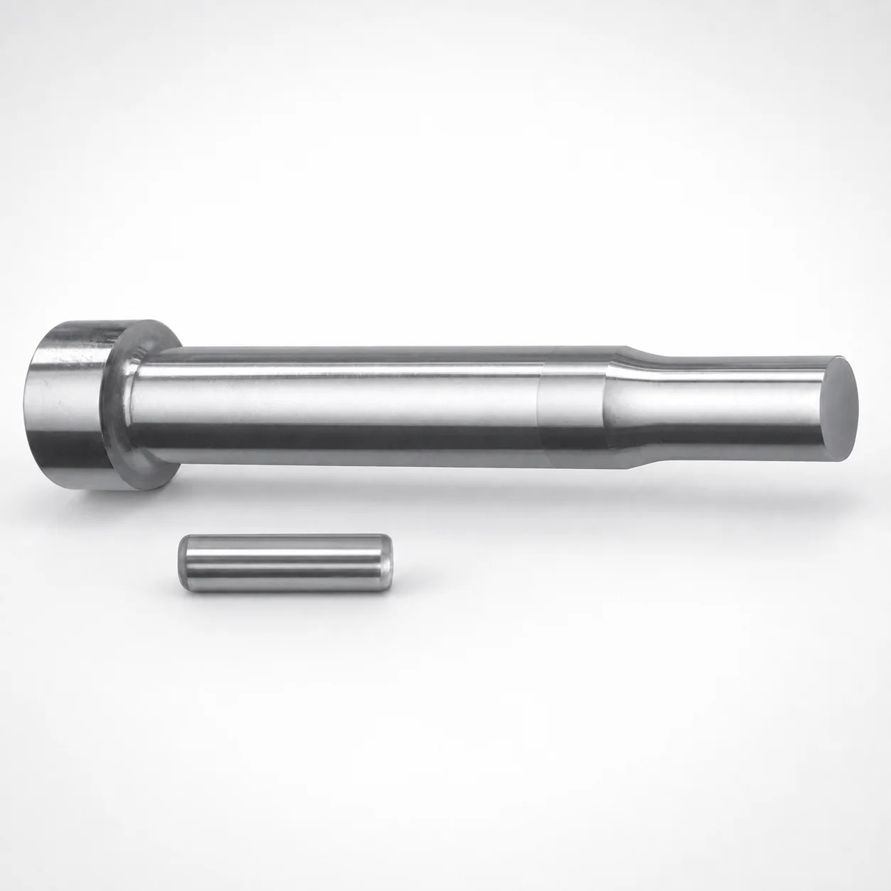
Center Dowel Punches for Heavy Load - Metric
Center Dowel Punches for Heavy Load - Metric (XNT DayTiN® coated) provide reliable alignment for die assemblies under demanding molding loads. Their heavy-load design supports stable centering and efficient setup.
- Centering dowel punch for heavy-load die alignment in production
- XNT DayTiN® coating helps reduce wear and extend service life
- Multiple tip shapes available to match different punch/insert interfaces
- Metric format shank and point dimensions support standardized tooling layouts
Specifications
164 configurations available
| Tip shape | D (Shank diameter) (mm) | L1 (Point Length) (mm) | L (Length) (mm) | P Dimension (mm) | W Dimension (mm) | R Dimension (mm) |
|---|---|---|---|---|---|---|
| H | 10 | 13 ~ 19 | 80 ~ 130 | 1.5 ~ 2.99 | 1.5 ~ 2.99 | - |
| H | 10 | 13 ~ 19 | 80 ~ 130 | 1.5 ~ 2.99 | 3 ~ 10 | - |
| H | 10 | 13 ~ 19 | 80 ~ 130 | 3 ~ 10 | 1.5 ~ 2.99 | - |
| H | 10 | 13 ~ 19 | 80 ~ 130 | 3 ~ 10 | 3 ~ 10 | - |
| H | 13 | 13 ~ 19 | 80 ~ 130 | 1.5 ~ 2.99 | 1.5 ~ 2.99 | - |
| H | 13 | 13 ~ 19 | 80 ~ 130 | 1.5 ~ 2.99 | 3 ~ 13 | - |
| H | 13 | 13 ~ 19 | 80 ~ 130 | 3 ~ 13 | 1.5 ~ 2.99 | - |
| H | 13 | 13 ~ 19 | 80 ~ 130 | 3 ~ 13 | 3 ~ 13 | - |
| H | 16 | 19 ~ 25 | 80 ~ 130 | 3 ~ 3.99 | 3 ~ 3.99 | - |
| H | 16 | 19 ~ 25 | 80 ~ 130 | 3 ~ 3.99 | 4 ~ 16 | - |
| H | 16 | 19 ~ 25 | 80 ~ 130 | 4 ~ 16 | 3 ~ 3.99 | - |
| H | 16 | 19 ~ 25 | 80 ~ 130 | 4 ~ 16 | 4 ~ 16 | - |
| H | 20 | 19 ~ 25 | 80 ~ 130 | 3 ~ 4.99 | 3 ~ 4.99 | - |
| H | 20 | 19 ~ 25 | 80 ~ 130 | 3 ~ 4.99 | 5 ~ 20 | - |
| H | 20 | 19 ~ 25 | 80 ~ 130 | 5 ~ 20 | 3 ~ 4.99 | - |
| H | 20 | 19 ~ 25 | 80 ~ 130 | 5 ~ 20 | 5 ~ 20 | - |
| H | 25 | 19 ~ 25 | 80 ~ 130 | 6 ~ 25 | 6 ~ 25 | - |
| J | 10 | 13 ~ 19 | 80 ~ 130 | 1.5 ~ 2.99 | 1.5 ~ 2.99 | - |
| J | 10 | 13 ~ 19 | 80 ~ 130 | 1.5 ~ 2.99 | 3 ~ 10 | - |
| J | 10 | 13 ~ 19 | 80 ~ 130 | 3 ~ 10 | 1.5 ~ 2.99 | - |
| J | 10 | 13 ~ 19 | 80 ~ 130 | 3 ~ 10 | 3 ~ 10 | - |
| J | 13 | 13 ~ 19 | 80 ~ 130 | 1.5 ~ 2.99 | 1.5 ~ 2.99 | - |
| J | 13 | 13 ~ 19 | 80 ~ 130 | 1.5 ~ 2.99 | 3 ~ 13 | - |
| J | 13 | 13 ~ 19 | 80 ~ 130 | 3 ~ 13 | 1.5 ~ 2.99 | - |
| J | 13 | 13 ~ 19 | 80 ~ 130 | 3 ~ 13 | 3 ~ 13 | - |
| J | 16 | 19 ~ 25 | 80 ~ 130 | 3 ~ 3.99 | 3 ~ 3.99 | - |
| J | 16 | 19 ~ 25 | 80 ~ 130 | 3 ~ 3.99 | 4 ~ 16 | - |
| J | 16 | 19 ~ 25 | 80 ~ 130 | 4 ~ 16 | 3 ~ 3.99 | - |
| J | 16 | 19 ~ 25 | 80 ~ 130 | 4 ~ 16 | 4 ~ 16 | - |
| J | 20 | 19 ~ 25 | 80 ~ 130 | 3 ~ 4.99 | 3 ~ 4.99 | - |
| J | 20 | 19 ~ 25 | 80 ~ 130 | 3 ~ 4.99 | 5 ~ 20 | - |
| J | 20 | 19 ~ 25 | 80 ~ 130 | 5 ~ 20 | 3 ~ 4.99 | - |
| J | 20 | 19 ~ 25 | 80 ~ 130 | 5 ~ 20 | 5 ~ 20 | - |
| J | 25 | 19 ~ 25 | 80 ~ 130 | 6 ~ 25 | 6 ~ 25 | - |
| K | 10 | 13 ~ 19 | 80 ~ 130 | 1.5 ~ 2.99 | 1.5 ~ 2.99 | 0.2 ~ 5 |
| K | 10 | 13 ~ 19 | 80 ~ 130 | 1.5 ~ 2.99 | 3 ~ 10 | 0.2 ~ 5 |
| K | 10 | 13 ~ 19 | 80 ~ 130 | 3 ~ 10 | 1.5 ~ 2.99 | 0.2 ~ 5 |
| K | 10 | 13 ~ 19 | 80 ~ 130 | 3 ~ 10 | 3 ~ 10 | 0.2 ~ 5 |
| K | 13 | 13 ~ 19 | 80 ~ 130 | 1.5 ~ 2.99 | 1.5 ~ 2.99 | 0.2 ~ 6.5 |
| K | 13 | 13 ~ 19 | 80 ~ 130 | 1.5 ~ 2.99 | 3 ~ 13 | 0.2 ~ 6.5 |
| K | 13 | 13 ~ 19 | 80 ~ 130 | 3 ~ 13 | 1.5 ~ 2.99 | 0.2 ~ 6.5 |
| K | 13 | 13 ~ 19 | 80 ~ 130 | 3 ~ 13 | 3 ~ 13 | 0.2 ~ 6.5 |
| K | 16 | 19 ~ 25 | 80 ~ 130 | 3 ~ 3.99 | 3 ~ 3.99 | 0.2 ~ 8 |
| K | 16 | 19 ~ 25 | 80 ~ 130 | 3 ~ 3.99 | 4 ~ 16 | 0.2 ~ 8 |
| K | 16 | 19 ~ 25 | 80 ~ 130 | 4 ~ 16 | 3 ~ 3.99 | 0.2 ~ 8 |
| K | 16 | 19 ~ 25 | 80 ~ 130 | 4 ~ 16 | 4 ~ 16 | 0.2 ~ 8 |
| K | 20 | 19 ~ 25 | 80 ~ 130 | 3 ~ 4.99 | 3 ~ 4.99 | 0.2 ~ 10 |
| K | 20 | 19 ~ 25 | 80 ~ 130 | 3 ~ 4.99 | 5 ~ 20 | 0.2 ~ 10 |
| K | 20 | 19 ~ 25 | 80 ~ 130 | 5 ~ 20 | 3 ~ 4.99 | 0.2 ~ 10 |
| K | 20 | 19 ~ 25 | 80 ~ 130 | 5 ~ 20 | 5 ~ 20 | 0.2 ~ 10 |
Product Guide
Application Scenarios+
Heavy-load center dowel punches are used in injection and stamping mold builds where repeatable die-to-die alignment is critical. This metric variant is typically installed in die/base plates to locate mating components during clamp cycles, helping maintain concentricity and reducing the risk of misalignment over high-volume production.
- Automotive connector and housing tooling: Use the dowel punches to stabilize multi-part inserts and runner block alignment under vibration and thermal expansion, leveraging the XNT DayTiN® coating for improved wear performance.
- Medical device housings and precision components: Reliable centering supports consistent cavity registration and uniform shut-off, which is important when tight dimensional control is required.
- High-cavitation molds and rapid changeover dies: The heavy-load design supports faster setup repeatability, while the available tip shapes help match different punch/insert interfaces for reliable seating.
The XNT DayTiN® coating and available tip geometries make this configuration well-suited for demanding production environments.
Material & Process Details+
The provided specification identifies this as a metric heavy-load center dowel punch series with an XNT DayTiN® coating. While the input data does not specify the underlying steel grade or heat treatment (e.g., quench-and-temper or nitriding), the coating is selected to improve surface durability in sliding/locating contact during repeated cycles.
- Coating effect: XNT DayTiN® is intended to increase wear resistance at the point/guide contact zone, helping maintain alignment accuracy and reducing fretting wear in die interfaces.
- Hardness & trade-offs: Coatings typically improve wear and reduce adhesion, but they rely on a sound substrate for toughness; overly brittle substrates can still chip under heavy loads.
When multiple steel/coating combinations are available, engineers should balance substrate toughness (for impact resistance during clamp) against surface wear protection (for long-term centering stability).
Sizing & Selection Guide+
Select the center dowel punch dimensions by matching the shank and locating features to the mating bushing/insert geometry in the mold base or die assembly. The series supports multiple tip shapes (H, J, K, L, N, O, R, V, X, Z) to fit different punch/insert interfaces—choose the tip shape that ensures full seating without interference.
- Shank diameter (D): Choose from 10, 13, 16, 20, 25 mm to match the locating bore/bushing diameter in the moving and fixed die plates.
- Point length (L1): Select within 13–19 mm or 19–25 mm based on required engagement depth for stable centering.
- Total length (L): Fixed at 80–130 mm; confirm clearance to avoid bottoming in the pocket or blind bore.
- Additional geometry (P, W, R): Use P = 1.5–18 mm, W = 1.5–6 mm, and R = 0.2–5 / 0.2–6.5 / 0.2–8 / 0.2–10 / 0.2–12.5 to match the mating profile requirements.
For press-fit or sliding locating designs, verify functional clearance and accommodate manufacturing tolerances so the dowels guide centering smoothly during clamp cycles.
Frequently Asked Questions
Which tip shape (H, J, K, L, N, O, R, V, X, Y, Z) should I select for my dowel/insert interface?+
How do I size the shank diameter (D) for the heavy-load center dowel punches?+
What point length (L1) should be used to ensure stable die centering?+
Are there sizing constraints for total length (L = 80–130 mm) in blind pockets or step-through plates?+
How does the XNT DayTiN® coating affect wear and alignment over repeated clamp cycles?+
Related Products

Metric Dowel Punches for Heavy Load with Single-Stepped Shank (M5)

Metric Center Dowel Punches for Heavy Load TiCN Coated

JIS Standard SKH51 Steel Ejector Punches for Heavy Load with Dowel Holes

SKH51 Steel TiCN Coating Ejector Punches for Heavy Load with Dowel Holes

RW Coated Dowel Punches for Heavy Load - Single-Stepped Shank

Center Dowel Ejector Punches for Heavy Load (RW Coating) - SKH51 Steel
Need Custom Specifications?
Our engineering team can help with custom configurations, material selection, and volume pricing.