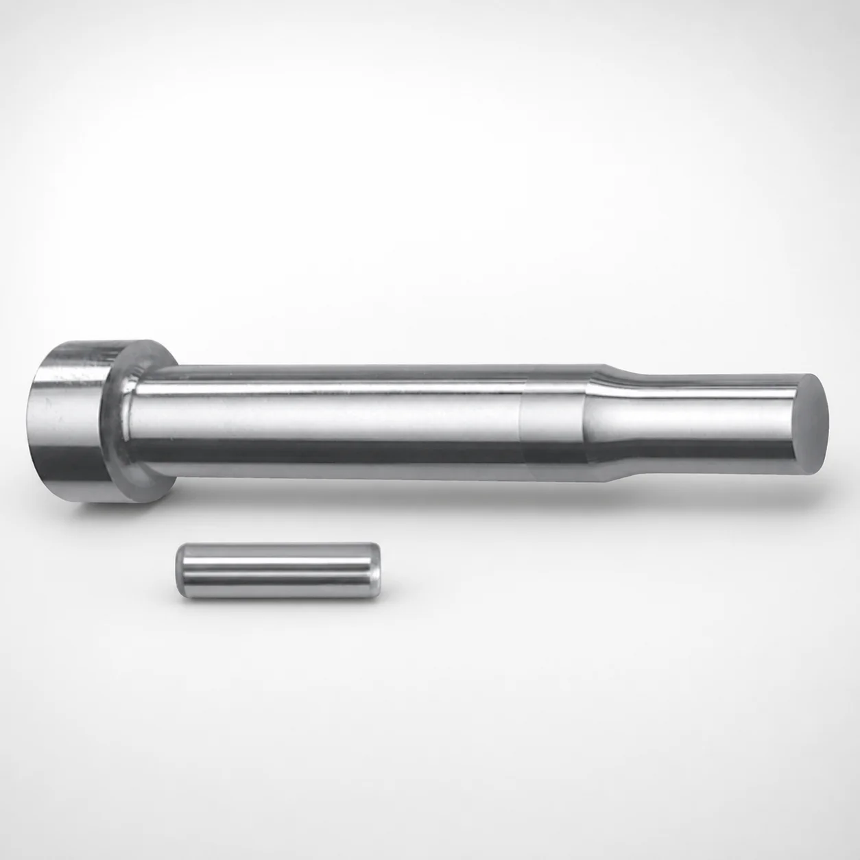
Metric Center Dowel Punches for Heavy Load (XNAP Coating)
Center Dowel Punches for Heavy Load (XNAP coating) are designed for reliable alignment and positioning in press tooling and heavy-duty fixture applications. The metric construction supports stable assembly under demanding cycles.
- Metric center dowel punch design for accurate part locating during operation
- XNAP coating helps improve wear resistance for extended tool life
- Controlled point geometry options for consistent engagement in die and punch sets
- Built for heavy-load mold and press components where repeatable registration matters
Specifications
164 configurations available
| Tip shape | D (Shank diameter) (mm) | L1 (Point Length) (mm) | L (Length) (mm) | P Dimension (mm) | W Dimension (mm) | R Dimension (mm) |
|---|---|---|---|---|---|---|
| H | 10 | 13 ~ 19 | 80 ~ 130 | 1.5 ~ 2.99 | 1.5 ~ 2.99 | - |
| H | 10 | 13 ~ 19 | 80 ~ 130 | 1.5 ~ 2.99 | 3 ~ 10 | - |
| H | 10 | 13 ~ 19 | 80 ~ 130 | 3 ~ 10 | 1.5 ~ 2.99 | - |
| H | 10 | 13 ~ 19 | 80 ~ 130 | 3 ~ 10 | 3 ~ 10 | - |
| H | 13 | 13 ~ 19 | 80 ~ 130 | 1.5 ~ 2.99 | 1.5 ~ 2.99 | - |
| H | 13 | 13 ~ 19 | 80 ~ 130 | 1.5 ~ 2.99 | 3 ~ 13 | - |
| H | 13 | 13 ~ 19 | 80 ~ 130 | 3 ~ 13 | 1.5 ~ 2.99 | - |
| H | 13 | 13 ~ 19 | 80 ~ 130 | 3 ~ 13 | 3 ~ 13 | - |
| H | 16 | 19 ~ 25 | 80 ~ 130 | 3 ~ 3.99 | 3 ~ 3.99 | - |
| H | 16 | 19 ~ 25 | 80 ~ 130 | 3 ~ 3.99 | 4 ~ 16 | - |
| H | 16 | 19 ~ 25 | 80 ~ 130 | 4 ~ 16 | 3 ~ 3.99 | - |
| H | 16 | 19 ~ 25 | 80 ~ 130 | 4 ~ 16 | 4 ~ 16 | - |
| H | 20 | 19 ~ 25 | 80 ~ 130 | 3 ~ 4.99 | 3 ~ 4.99 | - |
| H | 20 | 19 ~ 25 | 80 ~ 130 | 3 ~ 4.99 | 5 ~ 20 | - |
| H | 20 | 19 ~ 25 | 80 ~ 130 | 5 ~ 20 | 3 ~ 4.99 | - |
| H | 20 | 19 ~ 25 | 80 ~ 130 | 5 ~ 20 | 5 ~ 20 | - |
| H | 25 | 19 ~ 25 | 80 ~ 130 | 6 ~ 25 | 6 ~ 25 | - |
| J | 10 | 13 ~ 19 | 80 ~ 130 | 1.5 ~ 2.99 | 1.5 ~ 2.99 | - |
| J | 10 | 13 ~ 19 | 80 ~ 130 | 1.5 ~ 2.99 | 3 ~ 10 | - |
| J | 10 | 13 ~ 19 | 80 ~ 130 | 3 ~ 10 | 1.5 ~ 2.99 | - |
| J | 10 | 13 ~ 19 | 80 ~ 130 | 3 ~ 10 | 3 ~ 10 | - |
| J | 13 | 13 ~ 19 | 80 ~ 130 | 1.5 ~ 2.99 | 1.5 ~ 2.99 | - |
| J | 13 | 13 ~ 19 | 80 ~ 130 | 1.5 ~ 2.99 | 3 ~ 13 | - |
| J | 13 | 13 ~ 19 | 80 ~ 130 | 3 ~ 13 | 1.5 ~ 2.99 | - |
| J | 13 | 13 ~ 19 | 80 ~ 130 | 3 ~ 13 | 3 ~ 13 | - |
| J | 16 | 19 ~ 25 | 80 ~ 130 | 3 ~ 3.99 | 3 ~ 3.99 | - |
| J | 16 | 19 ~ 25 | 80 ~ 130 | 3 ~ 3.99 | 4 ~ 16 | - |
| J | 16 | 19 ~ 25 | 80 ~ 130 | 4 ~ 16 | 3 ~ 3.99 | - |
| J | 16 | 19 ~ 25 | 80 ~ 130 | 4 ~ 16 | 4 ~ 16 | - |
| J | 20 | 19 ~ 25 | 80 ~ 130 | 3 ~ 4.99 | 3 ~ 4.99 | - |
| J | 20 | 19 ~ 25 | 80 ~ 130 | 3 ~ 4.99 | 5 ~ 20 | - |
| J | 20 | 19 ~ 25 | 80 ~ 130 | 5 ~ 20 | 3 ~ 4.99 | - |
| J | 20 | 19 ~ 25 | 80 ~ 130 | 5 ~ 20 | 5 ~ 20 | - |
| J | 25 | 19 ~ 25 | 80 ~ 130 | 6 ~ 25 | 6 ~ 25 | - |
| K | 10 | 13 ~ 19 | 80 ~ 130 | 1.5 ~ 2.99 | 1.5 ~ 2.99 | 0.2 ~ 5 |
| K | 10 | 13 ~ 19 | 80 ~ 130 | 1.5 ~ 2.99 | 3 ~ 10 | 0.2 ~ 5 |
| K | 10 | 13 ~ 19 | 80 ~ 130 | 3 ~ 10 | 1.5 ~ 2.99 | 0.2 ~ 5 |
| K | 10 | 13 ~ 19 | 80 ~ 130 | 3 ~ 10 | 3 ~ 10 | 0.2 ~ 5 |
| K | 13 | 13 ~ 19 | 80 ~ 130 | 1.5 ~ 2.99 | 1.5 ~ 2.99 | 0.2 ~ 6.5 |
| K | 13 | 13 ~ 19 | 80 ~ 130 | 1.5 ~ 2.99 | 3 ~ 13 | 0.2 ~ 6.5 |
| K | 13 | 13 ~ 19 | 80 ~ 130 | 3 ~ 13 | 1.5 ~ 2.99 | 0.2 ~ 6.5 |
| K | 13 | 13 ~ 19 | 80 ~ 130 | 3 ~ 13 | 3 ~ 13 | 0.2 ~ 6.5 |
| K | 16 | 19 ~ 25 | 80 ~ 130 | 3 ~ 3.99 | 3 ~ 3.99 | 0.2 ~ 8 |
| K | 16 | 19 ~ 25 | 80 ~ 130 | 3 ~ 3.99 | 4 ~ 16 | 0.2 ~ 8 |
| K | 16 | 19 ~ 25 | 80 ~ 130 | 4 ~ 16 | 3 ~ 3.99 | 0.2 ~ 8 |
| K | 16 | 19 ~ 25 | 80 ~ 130 | 4 ~ 16 | 4 ~ 16 | 0.2 ~ 8 |
| K | 20 | 19 ~ 25 | 80 ~ 130 | 3 ~ 4.99 | 3 ~ 4.99 | 0.2 ~ 10 |
| K | 20 | 19 ~ 25 | 80 ~ 130 | 3 ~ 4.99 | 5 ~ 20 | 0.2 ~ 10 |
| K | 20 | 19 ~ 25 | 80 ~ 130 | 5 ~ 20 | 3 ~ 4.99 | 0.2 ~ 10 |
| K | 20 | 19 ~ 25 | 80 ~ 130 | 5 ~ 20 | 5 ~ 20 | 0.2 ~ 10 |
Product Guide
Application Scenarios+
These metric center dowel punches are used in injection mold tooling and press systems where repeatable alignment directly impacts part quality and tool life. They act as a hardened locating element during die/punch assembly, helping maintain registration during high-cycle operation.
- Automotive and industrial connector molds: used in heavy-duty mold bases and multi-cavity setups to keep cavity spacing consistent while withstanding rapid shut-off cycles.
- Medical device housings and precision components: support stable positioning of inserts and fixture plates, reducing the risk of misalignment that can affect surface finish and critical tolerances.
- High-load transfer/fixture tooling: the XNAP coating variant is suited for areas with elevated sliding wear, improving durability at the interface where the punch point repeatedly engages.
Choose the appropriate tip shape (H, J, K, L, N, O, R, V, X, or Y/Z) to match engagement geometry in your die and punch sets for consistent seating and repeatable location.
Material & Process Details+
The provided specification describes the geometry and XNAP coating, but does not list the underlying steel grade or hardness values. In practice, center dowel punches for heavy-load alignment are typically manufactured from tool steel and finished to resist indentation and fretting at the locating interface.
- XNAP coating: selected to improve wear resistance for longer service life under repeated engagement.
- Hardness & trade-offs: higher surface hardness improves wear and point stability, while adequate core toughness is needed to avoid chipping at the point during heavy load cycles (material grade and heat treatment determine the balance).
- Heat treatment state: usually supplied in a hardened condition with subsequent coating; exact tempering parameters are not provided in the current data.
If you share the steel grade option offered by your quotation, we can map it to the corresponding hardness (HRC) and recommend whether additional surface hardening (e.g., nitriding/oxide control) is needed for your duty cycle.
Sizing & Selection Guide+
Select the dowel punch dimensions to match your mold alignment scheme between the mating die and punch halves. Start with D (shank diameter) in the available metric sizes 10, 13, 16, 20, 25 mm, ensuring the mating reamed hole or bushing bore provides the required clearance or press fit per your design practice.
- L (overall length): fixed in the range 80–130 mm. Choose a length that provides full seating engagement without bottoming in the stack-up.
- L1 (point length): choose based on required penetration depth, available as 13–19 mm, 19–25 mm, or 19–25 mm (listed as overlapping ranges). This controls how consistently the point transfers location during shut-off.
- P, W, R geometry: match the specified P (1.5–18 mm), W (1.5–6 mm), and R (0.2–5 / 0.2–6.5 / 0.2–8 / 0.2–10 / 0.2–12.5 mm) to your cavity/core pocket profile.
Tip shape (H/J/K/L/N/O/R/V/X/Y/Z) should be selected to ensure consistent engagement and predictable seating under load. Consider tolerance stack-up across the tool stack when setting bore size and length engagement.
Frequently Asked Questions
Which tip shape (H, J, K, L, N, O, R, V, X, Y, Z) should I use for consistent location in die-to-punch alignment?+
How do I choose the correct shank diameter D for this metric heavy-load dowel punch?+
What guidance do I have for selecting L and point length L1 to match cavity/core stack-up?+
How do P, W, and R dimensions relate to the mating pocket geometry?+
What does the XNAP coating improve for heavy-load alignment features?+
Related Products

Metric Dowel Punches for Heavy Load with Single-Stepped Shank (M5)

Metric Center Dowel Punches for Heavy Load TiCN Coated

JIS Standard SKH51 Steel Ejector Punches for Heavy Load with Dowel Holes

SKH51 Steel TiCN Coating Ejector Punches for Heavy Load with Dowel Holes

RW Coated Dowel Punches for Heavy Load - Single-Stepped Shank

Center Dowel Ejector Punches for Heavy Load (RW Coating) - SKH51 Steel
Need Custom Specifications?
Our engineering team can help with custom configurations, material selection, and volume pricing.