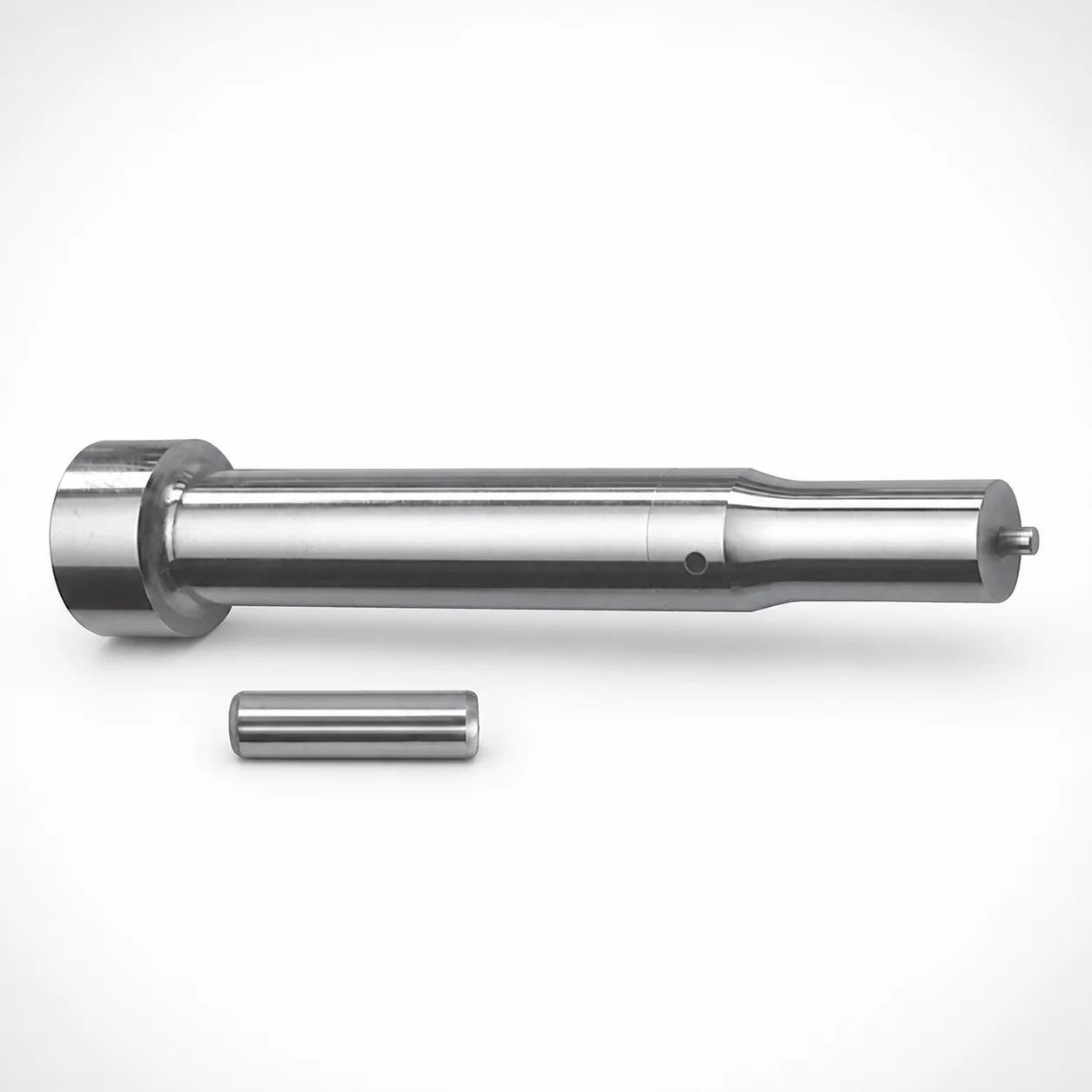
Metric XNAD Coating Center Dowel Punches for Heavy Load
Center Dowel Punches for Heavy Load (Metric) with XNAD Coating are built for accurate center marking and robust dowel-hole alignment in demanding mold and die assembly tasks. The punch design supports repeatable positioning under heavy load conditions.
- Heavy-load center punching for dependable dowel-hole alignment
- XNAD coating helps reduce wear and improves durability for longer service intervals
- Optimized geometry supports secure seating and stable operation across typical metric builds
- Designed for heavy-duty industrial applications where consistent setup accuracy matters
Specifications
112 configurations available
| Tip shape | D (Shank diameter) (mm) | Jektole group | L1 (Point Length) (mm) | L (Length) (mm) | P Dimension (mm) | W Dimension (mm) | R Dimension (mm) |
|---|---|---|---|---|---|---|---|
| H | 10 | J6M | 13 ~ 19 | 80 ~ 130 | 4 ~ 4.99 | 4 ~ 4.99 | - |
| H | 10 | J6M | 13 ~ 19 | 80 ~ 130 | 4 ~ 4.99 | 5 ~ 10 | - |
| H | 10 | J6M | 13 ~ 19 | 80 ~ 130 | 5 ~ 10 | 4 ~ 4.99 | - |
| H | 10 | J6M | 13 ~ 19 | 80 ~ 130 | 5 ~ 10 | 5 ~ 10 | - |
| H | 13 | J6M | 13 ~ 19 | 80 ~ 130 | 4 ~ 5.99 | 4 ~ 5.99 | - |
| H | 13 | J6M | 13 ~ 19 | 80 ~ 130 | 4 ~ 5.99 | 6 ~ 13 | - |
| H | 13 | J6M | 13 ~ 19 | 80 ~ 130 | 6 ~ 13 | 4 ~ 5.99 | - |
| H | 13 | J6M | 13 ~ 19 | 80 ~ 130 | 6 ~ 13 | 6 ~ 13 | - |
| H | 16 | J9M | 19 ~ 25 | 80 ~ 130 | 6 ~ 16 | 6 ~ 16 | - |
| H | 20 | J9M | 19 ~ 25 | 80 ~ 130 | 6 ~ 20 | 6 ~ 20 | - |
| H | 25 | J9M | 19 ~ 25 | 80 ~ 130 | 6 ~ 25 | 6 ~ 25 | - |
| J | 10 | J6M | 13 ~ 19 | 80 ~ 130 | 4 ~ 4.99 | 4 ~ 4.99 | - |
| J | 10 | J6M | 13 ~ 19 | 80 ~ 130 | 4 ~ 4.99 | 5 ~ 10 | - |
| J | 10 | J6M | 13 ~ 19 | 80 ~ 130 | 5 ~ 10 | 4 ~ 4.99 | - |
| J | 10 | J6M | 13 ~ 19 | 80 ~ 130 | 5 ~ 10 | 5 ~ 10 | - |
| J | 13 | J6M | 13 ~ 19 | 80 ~ 130 | 4 ~ 5.99 | 4 ~ 5.99 | - |
| J | 13 | J6M | 13 ~ 19 | 80 ~ 130 | 4 ~ 5.99 | 6 ~ 13 | - |
| J | 13 | J6M | 13 ~ 19 | 80 ~ 130 | 6 ~ 13 | 4 ~ 5.99 | - |
| J | 13 | J6M | 13 ~ 19 | 80 ~ 130 | 6 ~ 13 | 6 ~ 13 | - |
| J | 16 | J9M | 19 ~ 25 | 80 ~ 130 | 6 ~ 16 | 6 ~ 16 | - |
| J | 20 | J9M | 19 ~ 25 | 80 ~ 130 | 6 ~ 20 | 6 ~ 20 | - |
| J | 25 | J9M | 19 ~ 25 | 80 ~ 130 | 6 ~ 25 | 6 ~ 25 | - |
| K | 10 | J6M | 13 ~ 19 | 80 ~ 130 | 4 ~ 4.99 | 4 ~ 4.99 | 0.2 ~ 5 |
| K | 10 | J6M | 13 ~ 19 | 80 ~ 130 | 4 ~ 4.99 | 5 ~ 10 | 0.2 ~ 5 |
| K | 10 | J6M | 13 ~ 19 | 80 ~ 130 | 5 ~ 10 | 4 ~ 4.99 | 0.2 ~ 5 |
| K | 10 | J6M | 13 ~ 19 | 80 ~ 130 | 5 ~ 10 | 5 ~ 10 | 0.2 ~ 5 |
| K | 13 | J6M | 13 ~ 19 | 80 ~ 130 | 4 ~ 5.99 | 4 ~ 5.99 | 0.2 ~ 6.5 |
| K | 13 | J6M | 13 ~ 19 | 80 ~ 130 | 4 ~ 5.99 | 6 ~ 13 | 0.2 ~ 6.5 |
| K | 13 | J6M | 13 ~ 19 | 80 ~ 130 | 6 ~ 13 | 4 ~ 5.99 | 0.2 ~ 6.5 |
| K | 13 | J6M | 13 ~ 19 | 80 ~ 130 | 6 ~ 13 | 6 ~ 13 | 0.2 ~ 6.5 |
| K | 16 | J9M | 19 ~ 25 | 80 ~ 130 | 6 ~ 16 | 6 ~ 16 | 0.2 ~ 8 |
| K | 20 | J9M | 19 ~ 25 | 80 ~ 130 | 6 ~ 20 | 6 ~ 20 | 0.2 ~ 10 |
| K | 25 | J9M | 19 ~ 25 | 80 ~ 130 | 6 ~ 25 | 6 ~ 25 | 0.2 ~ 12.5 |
| L | 10 | J6M | 13 ~ 19 | 80 ~ 130 | 4 ~ 4.99 | 4 ~ 4.99 | - |
| L | 10 | J6M | 13 ~ 19 | 80 ~ 130 | 4 ~ 4.99 | 5 ~ 10 | - |
| L | 10 | J6M | 13 ~ 19 | 80 ~ 130 | 5 ~ 10 | 4 ~ 4.99 | - |
| L | 10 | J6M | 13 ~ 19 | 80 ~ 130 | 5 ~ 10 | 5 ~ 10 | - |
| L | 13 | J6M | 13 ~ 19 | 80 ~ 130 | 4 ~ 5.99 | 4 ~ 5.99 | - |
| L | 13 | J6M | 13 ~ 19 | 80 ~ 130 | 4 ~ 5.99 | 6 ~ 13 | - |
| L | 13 | J6M | 13 ~ 19 | 80 ~ 130 | 6 ~ 13 | 4 ~ 5.99 | - |
| L | 13 | J6M | 13 ~ 19 | 80 ~ 130 | 6 ~ 13 | 6 ~ 13 | - |
| L | 16 | J9M | 19 ~ 25 | 80 ~ 130 | 6 ~ 16 | 6 ~ 16 | - |
| L | 20 | J9M | 19 ~ 25 | 80 ~ 130 | 6 ~ 20 | 6 ~ 20 | - |
| L | 25 | J9M | 19 ~ 25 | 80 ~ 130 | 6 ~ 25 | 6 ~ 25 | - |
| N | 10 | J6M | 13 ~ 19 | 80 ~ 130 | - | 4 ~ 4.99 | - |
| N | 10 | J6M | 13 ~ 19 | 80 ~ 130 | - | 5 ~ 10 | - |
| N | 13 | J6M | 13 ~ 19 | 80 ~ 130 | - | 4 ~ 5.99 | - |
| N | 13 | J6M | 13 ~ 19 | 80 ~ 130 | - | 6 ~ 13 | - |
| N | 16 | J9M | 19 ~ 25 | 80 ~ 130 | - | 6 ~ 16 | - |
| N | 20 | J9M | 19 ~ 25 | 80 ~ 130 | - | 6 ~ 20 | - |
Product Guide
Application Scenarios+
Center dowel punches are used in injection mold and die assembly to create repeatable reference points for locating dowel pins and ensuring cavity/core alignment. In heavy-load automotive connector molds, this style supports consistent center marking so the dowel-hole layout stays stable during repeated tryouts and clamp cycles.
For medical device housings and other precision parts, accurate dowel-hole setup reduces cumulative misalignment between halves and helps maintain dimensional stability across production runs. The heavy-duty geometry, combined with the XNAD coating, is suited to longer tooling service intervals where punch wear would otherwise degrade edge sharpness and center accuracy.
- Automotive connector molds: reliable dowel-hole alignment under high assembly forces.
- Medical device housings: repeatable reference marking to reduce half-to-half variation.
- Industrial die builds: durable punching performance for frequent maintenance cycles.
Material & Process Details+
These metric center dowel punches use an XNAD coating intended to improve wear resistance at the punch tip during repeated contact and hole setup operations. While the exact base steel grade is not specified in the provided data, the coating’s primary function is to support harder, longer-lasting contact behavior by reducing abrasion and edge degradation.
- Wear resistance vs. toughness: XNAD helps preserve tip condition and punching stability, which supports accurate center marking over time.
- Heat treatment state: not specified in the provided information; the coating is applied to the punch surface to enhance service life without requiring changes to the dimensional selection process.
- Tip shape options: H, J, K, L, N, O, R, V, X, Y, Z allow matching the contact/marking profile to your jig or dowel-hole workflow.
For applications requiring extreme abrasion resistance, compare coating variants when available; when using the same series, the coating offers the consistent durability lever most directly tied to tip wear.
Sizing & Selection Guide+
Select the punch dimensions by matching your dowel-hole setup and center marking requirements to the listed metric ranges. Start with the required shank diameter D (10, 13, 16, 20, 25 mm), then confirm the point length L1 to achieve the desired penetration or marking depth (13–19 mm or 19–25 mm).
The overall length L is fixed at 80–130 mm, which you must verify against the available tool clearance between mold plates and the assembly tooling interface. Choose the correct tip shape (H, J, K, L, N, O, R, V, X, Y, Z) and then verify the related geometry parameters: P (4–18 mm), W (4–6 mm), and R (0.2–5, 0.2–6.5, 0.2–8, 0.2–10, 0.2–12.5) to align with your centering feature tolerances.
- Fixed vs. variable: L is specified as 80–130 mm, while D, L1, P, W, R, and tip shape are variable.
- Fit considerations: for dowel-hole location repeatability, ensure the punch’s D and tip geometry match the locating system and fixture clearances; minor variance in centering features can affect alignment.
Frequently Asked Questions
Which shank diameter D options are available for this metric heavy-load center dowel punch series?+
How do I choose the point length L1 for correct center marking depth?+
Is the overall punch length L fixed or variable in this product specification?+
What tip shapes are offered, and when would I select different shapes (H/J/K/L/N/O/R/V/X/Y/Z)?+
What coating is specified for heavy-duty wear resistance, and how does it relate to performance?+
Related Products

Metric Dowel Punches for Heavy Load with Single-Stepped Shank (M5)

Metric Center Dowel Punches for Heavy Load TiCN Coated

JIS Standard SKH51 Steel Ejector Punches for Heavy Load with Dowel Holes

SKH51 Steel TiCN Coating Ejector Punches for Heavy Load with Dowel Holes

RW Coated Dowel Punches for Heavy Load - Single-Stepped Shank

Center Dowel Ejector Punches for Heavy Load (RW Coating) - SKH51 Steel
Need Custom Specifications?
Our engineering team can help with custom configurations, material selection, and volume pricing.