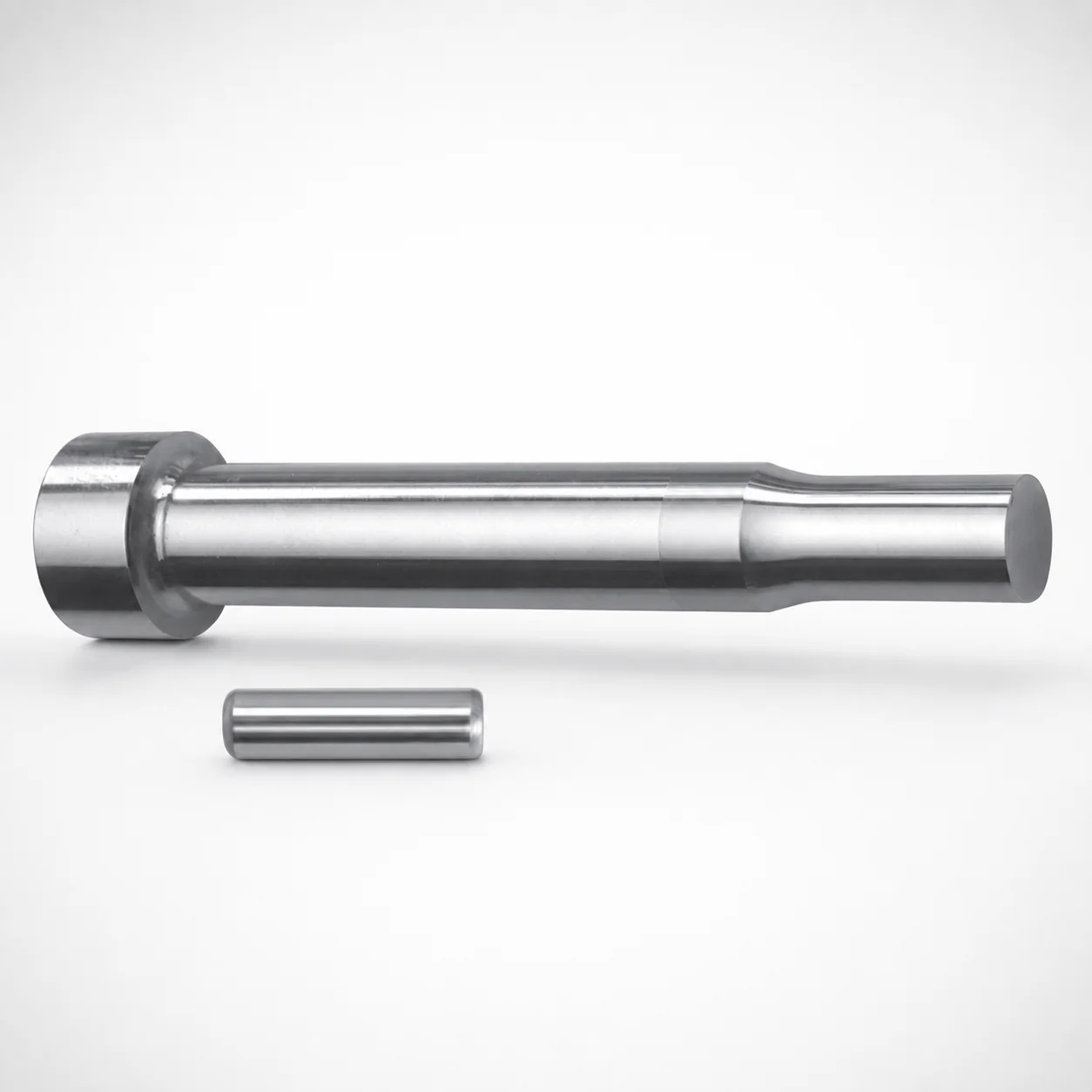
Center Dowel Punches for Heavy Load Metric XNAD Coating
Center Dowel Punches for Heavy Load Metric (XNAD coating) are designed for stable centering and die alignment under high load. The coating supports wear resistance for longer punch service life.
- Heavy-load center dowel punch geometry for accurate locating during die operations
- XNAD coating helps improve surface durability in demanding forming environments
- Tip shapes are available in multiple profiles to match specific die center hole requirements
- Metric punch body supports consistent assembly for long-stroke and production die sets
Specifications
164 configurations available
| Tip shape | D (Shank diameter) (mm) | L1 (Point Length) (mm) | L (Length) (mm) | P Dimension (mm) | W Dimension (mm) | R Dimension (mm) |
|---|---|---|---|---|---|---|
| H | 10 | 13 ~ 19 | 80 ~ 130 | 1.5 ~ 2.99 | 1.5 ~ 2.99 | - |
| H | 10 | 13 ~ 19 | 80 ~ 130 | 1.5 ~ 2.99 | 3 ~ 10 | - |
| H | 10 | 13 ~ 19 | 80 ~ 130 | 3 ~ 10 | 1.5 ~ 2.99 | - |
| H | 10 | 13 ~ 19 | 80 ~ 130 | 3 ~ 10 | 3 ~ 10 | - |
| H | 13 | 13 ~ 19 | 80 ~ 130 | 1.5 ~ 2.99 | 1.5 ~ 2.99 | - |
| H | 13 | 13 ~ 19 | 80 ~ 130 | 1.5 ~ 2.99 | 3 ~ 13 | - |
| H | 13 | 13 ~ 19 | 80 ~ 130 | 3 ~ 13 | 1.5 ~ 2.99 | - |
| H | 13 | 13 ~ 19 | 80 ~ 130 | 3 ~ 13 | 3 ~ 13 | - |
| H | 16 | 19 ~ 25 | 80 ~ 130 | 3 ~ 3.99 | 3 ~ 3.99 | - |
| H | 16 | 19 ~ 25 | 80 ~ 130 | 3 ~ 3.99 | 4 ~ 16 | - |
| H | 16 | 19 ~ 25 | 80 ~ 130 | 4 ~ 16 | 3 ~ 3.99 | - |
| H | 16 | 19 ~ 25 | 80 ~ 130 | 4 ~ 16 | 4 ~ 16 | - |
| H | 20 | 19 ~ 25 | 80 ~ 130 | 3 ~ 4.99 | 3 ~ 4.99 | - |
| H | 20 | 19 ~ 25 | 80 ~ 130 | 3 ~ 4.99 | 5 ~ 20 | - |
| H | 20 | 19 ~ 25 | 80 ~ 130 | 5 ~ 20 | 3 ~ 4.99 | - |
| H | 20 | 19 ~ 25 | 80 ~ 130 | 5 ~ 20 | 5 ~ 20 | - |
| H | 25 | 19 ~ 25 | 80 ~ 130 | 6 ~ 25 | 6 ~ 25 | - |
| J | 10 | 13 ~ 19 | 80 ~ 130 | 1.5 ~ 2.99 | 1.5 ~ 2.99 | - |
| J | 10 | 13 ~ 19 | 80 ~ 130 | 1.5 ~ 2.99 | 3 ~ 10 | - |
| J | 10 | 13 ~ 19 | 80 ~ 130 | 3 ~ 10 | 1.5 ~ 2.99 | - |
| J | 10 | 13 ~ 19 | 80 ~ 130 | 3 ~ 10 | 3 ~ 10 | - |
| J | 13 | 13 ~ 19 | 80 ~ 130 | 1.5 ~ 2.99 | 1.5 ~ 2.99 | - |
| J | 13 | 13 ~ 19 | 80 ~ 130 | 1.5 ~ 2.99 | 3 ~ 13 | - |
| J | 13 | 13 ~ 19 | 80 ~ 130 | 3 ~ 13 | 1.5 ~ 2.99 | - |
| J | 13 | 13 ~ 19 | 80 ~ 130 | 3 ~ 13 | 3 ~ 13 | - |
| J | 16 | 19 ~ 25 | 80 ~ 130 | 3 ~ 3.99 | 3 ~ 3.99 | - |
| J | 16 | 19 ~ 25 | 80 ~ 130 | 3 ~ 3.99 | 4 ~ 16 | - |
| J | 16 | 19 ~ 25 | 80 ~ 130 | 4 ~ 16 | 3 ~ 3.99 | - |
| J | 16 | 19 ~ 25 | 80 ~ 130 | 4 ~ 16 | 4 ~ 16 | - |
| J | 20 | 19 ~ 25 | 80 ~ 130 | 3 ~ 4.99 | 3 ~ 4.99 | - |
| J | 20 | 19 ~ 25 | 80 ~ 130 | 3 ~ 4.99 | 5 ~ 20 | - |
| J | 20 | 19 ~ 25 | 80 ~ 130 | 5 ~ 20 | 3 ~ 4.99 | - |
| J | 20 | 19 ~ 25 | 80 ~ 130 | 5 ~ 20 | 5 ~ 20 | - |
| J | 25 | 19 ~ 25 | 80 ~ 130 | 6 ~ 25 | 6 ~ 25 | - |
| K | 10 | 13 ~ 19 | 80 ~ 130 | 1.5 ~ 2.99 | 1.5 ~ 2.99 | 0.2 ~ 5 |
| K | 10 | 13 ~ 19 | 80 ~ 130 | 1.5 ~ 2.99 | 3 ~ 10 | 0.2 ~ 5 |
| K | 10 | 13 ~ 19 | 80 ~ 130 | 3 ~ 10 | 1.5 ~ 2.99 | 0.2 ~ 5 |
| K | 10 | 13 ~ 19 | 80 ~ 130 | 3 ~ 10 | 3 ~ 10 | 0.2 ~ 5 |
| K | 13 | 13 ~ 19 | 80 ~ 130 | 1.5 ~ 2.99 | 1.5 ~ 2.99 | 0.2 ~ 6.5 |
| K | 13 | 13 ~ 19 | 80 ~ 130 | 1.5 ~ 2.99 | 3 ~ 13 | 0.2 ~ 6.5 |
| K | 13 | 13 ~ 19 | 80 ~ 130 | 3 ~ 13 | 1.5 ~ 2.99 | 0.2 ~ 6.5 |
| K | 13 | 13 ~ 19 | 80 ~ 130 | 3 ~ 13 | 3 ~ 13 | 0.2 ~ 6.5 |
| K | 16 | 19 ~ 25 | 80 ~ 130 | 3 ~ 3.99 | 3 ~ 3.99 | 0.2 ~ 8 |
| K | 16 | 19 ~ 25 | 80 ~ 130 | 3 ~ 3.99 | 4 ~ 16 | 0.2 ~ 8 |
| K | 16 | 19 ~ 25 | 80 ~ 130 | 4 ~ 16 | 3 ~ 3.99 | 0.2 ~ 8 |
| K | 16 | 19 ~ 25 | 80 ~ 130 | 4 ~ 16 | 4 ~ 16 | 0.2 ~ 8 |
| K | 20 | 19 ~ 25 | 80 ~ 130 | 3 ~ 4.99 | 3 ~ 4.99 | 0.2 ~ 10 |
| K | 20 | 19 ~ 25 | 80 ~ 130 | 3 ~ 4.99 | 5 ~ 20 | 0.2 ~ 10 |
| K | 20 | 19 ~ 25 | 80 ~ 130 | 5 ~ 20 | 3 ~ 4.99 | 0.2 ~ 10 |
| K | 20 | 19 ~ 25 | 80 ~ 130 | 5 ~ 20 | 5 ~ 20 | 0.2 ~ 10 |
Product Guide
Application Scenarios+
These heavy-load center dowel punches are used in injection and forming tooling where repeatable die alignment is critical. They act as robust locating elements between die halves, helping maintain concentricity when press force or clamping loads are high.
- Automotive connector and bracket tooling: During multi-cavity production, the punch’s heavy-load geometry supports consistent centering so cores/cavities stay aligned through long production runs. The XNAD coating improves surface durability in abrasive, high-cycle environments.
- Industrial appliance and housing molds: For housings with larger parting surfaces, these punches help prevent drift and reduce mislocation-related flashes. The metric shank sizing supports reliable assembly across standard die sets.
- Die work requiring precise center hole transfer: Available tip shapes (H, J, K, L, N, O, R, V, X, Y, Z) allow matching to specific center-hole profiles, improving force transfer and centering stability during setup and operation.
Material & Process Details+
The provided data specifies an XNAD coating for heavy-duty alignment and wear resistance, but it does not list the underlying steel grade or heat-treatment condition (e.g., quenched & tempered, nitrided) for this series. Therefore, material property values such as hardness (HRC) and specific wear/toughness trade-offs cannot be stated from the available specifications.
What can be confirmed is the functional role of the XNAD coating: it is applied to enhance surface durability of the centering interface under demanding forming/insertion conditions. This typically benefits applications where fretting or abrasive wear would otherwise degrade locating surfaces and increase positional variation.
- Coating-focused performance: XNAD targets wear resistance at the working tip and shank interface.
- Selection note: If you require a specific steel grade or target hardness (HRC) for your mold standard, request the datasheet for the base material and heat treatment.
Sizing & Selection Guide+
Select dimensions by matching the punch to your die set locating requirements and center-hole geometry. This series uses a fixed overall length L = 80–130 mm, so choose L based on your tool thickness and engagement depth between die plates.
- Shank diameter D (mm): Choose from 10, 13, 16, 20, 25 to fit the corresponding guide/bushing clearance and keep centering repeatable.
- Point length L1 (mm): Select based on how much the working tip must enter the center hole. Available ranges are 13–19, 19–25, and 19–25 (as listed in the data).
- Tip shapes: Pick the specific tip shape (H, J, K, L, N, O, R, V, X, Y, Z) that matches the mating center-hole profile for accurate force transfer.
- Fine geometry parameters: Ensure P = 1.5–18 mm, W = 1.5–6 mm, and R = 0.2–5 / 0.2–6.5 / 0.2–8 / 0.2–10 / 0.2–12.5 align with your drawing and clearance requirements.
Tolerance/fit specifics are not provided in the input data. Use your die designer’s standard clearance limits for dowel engagement and verify that shank diameter D and tip profile will not interfere at full clamping.
Frequently Asked Questions
Which tip shapes (H, J, K, L, N, O, R, V, X, Y, Z) should I select for a specific center-hole geometry?+
How do I choose L and L1 for proper engagement without bottoming out?+
What shank diameter D options are available, and how do they affect locating accuracy?+
Can you provide hardness (HRC) and heat-treatment details for this heavy-load center dowel punch series?+
How do the P, W, and R parameters relate to clearance and durability at the die interface?+
Related Products

Metric Dowel Punches for Heavy Load with Single-Stepped Shank (M5)

Metric Center Dowel Punches for Heavy Load TiCN Coated

JIS Standard SKH51 Steel Ejector Punches for Heavy Load with Dowel Holes

SKH51 Steel TiCN Coating Ejector Punches for Heavy Load with Dowel Holes

RW Coated Dowel Punches for Heavy Load - Single-Stepped Shank

Center Dowel Ejector Punches for Heavy Load (RW Coating) - SKH51 Steel
Need Custom Specifications?
Our engineering team can help with custom configurations, material selection, and volume pricing.