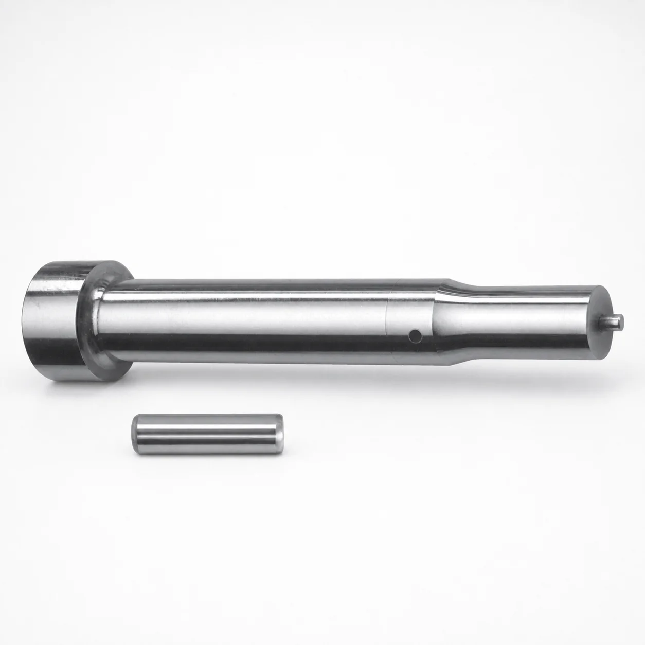
Center Dowel Punches for Heavy Load (Metric) with XNA Coating
Center Dowel Punches for Heavy Load (Metric) with XNA Coating are engineered for stable dowel-hole alignment in heavy duty die and mold assembly. The center-tip design helps position accurately and reliably throughout repeated cycles.
- Heavy-load center dowel punch format for consistent positioning
- XNA coating supports improved wear resistance for long service life
- Metric configurations with selectable tip shapes to match tooling requirements
- Designed for die maintenance and production applications
Specifications
112 configurations available
| Tip shape | D (Shank diameter) (mm) | Jektole group | L1 (Point Length) (mm) | L (Length) (mm) | P Dimension (mm) | W Dimension (mm) | R Dimension (mm) |
|---|---|---|---|---|---|---|---|
| H | 10 | J6M | 13 ~ 19 | 80 ~ 130 | 4 ~ 4.99 | 4 ~ 4.99 | - |
| H | 10 | J6M | 13 ~ 19 | 80 ~ 130 | 4 ~ 4.99 | 5 ~ 10 | - |
| H | 10 | J6M | 13 ~ 19 | 80 ~ 130 | 5 ~ 10 | 4 ~ 4.99 | - |
| H | 10 | J6M | 13 ~ 19 | 80 ~ 130 | 5 ~ 10 | 5 ~ 10 | - |
| H | 13 | J6M | 13 ~ 19 | 80 ~ 130 | 4 ~ 5.99 | 4 ~ 5.99 | - |
| H | 13 | J6M | 13 ~ 19 | 80 ~ 130 | 4 ~ 5.99 | 6 ~ 13 | - |
| H | 13 | J6M | 13 ~ 19 | 80 ~ 130 | 6 ~ 13 | 4 ~ 5.99 | - |
| H | 13 | J6M | 13 ~ 19 | 80 ~ 130 | 6 ~ 13 | 6 ~ 13 | - |
| H | 16 | J9M | 19 ~ 25 | 80 ~ 130 | 6 ~ 16 | 6 ~ 16 | - |
| H | 20 | J9M | 19 ~ 25 | 80 ~ 130 | 6 ~ 20 | 6 ~ 20 | - |
| H | 25 | J9M | 19 ~ 25 | 80 ~ 130 | 6 ~ 25 | 6 ~ 25 | - |
| J | 10 | J6M | 13 ~ 19 | 80 ~ 130 | 4 ~ 4.99 | 4 ~ 4.99 | - |
| J | 10 | J6M | 13 ~ 19 | 80 ~ 130 | 4 ~ 4.99 | 5 ~ 10 | - |
| J | 10 | J6M | 13 ~ 19 | 80 ~ 130 | 5 ~ 10 | 4 ~ 4.99 | - |
| J | 10 | J6M | 13 ~ 19 | 80 ~ 130 | 5 ~ 10 | 5 ~ 10 | - |
| J | 13 | J6M | 13 ~ 19 | 80 ~ 130 | 4 ~ 5.99 | 4 ~ 5.99 | - |
| J | 13 | J6M | 13 ~ 19 | 80 ~ 130 | 4 ~ 5.99 | 6 ~ 13 | - |
| J | 13 | J6M | 13 ~ 19 | 80 ~ 130 | 6 ~ 13 | 4 ~ 5.99 | - |
| J | 13 | J6M | 13 ~ 19 | 80 ~ 130 | 6 ~ 13 | 6 ~ 13 | - |
| J | 16 | J9M | 19 ~ 25 | 80 ~ 130 | 6 ~ 16 | 6 ~ 16 | - |
| J | 20 | J9M | 19 ~ 25 | 80 ~ 130 | 6 ~ 20 | 6 ~ 20 | - |
| J | 25 | J9M | 19 ~ 25 | 80 ~ 130 | 6 ~ 25 | 6 ~ 25 | - |
| K | 10 | J6M | 13 ~ 19 | 80 ~ 130 | 4 ~ 4.99 | 4 ~ 4.99 | 0.2 ~ 5 |
| K | 10 | J6M | 13 ~ 19 | 80 ~ 130 | 4 ~ 4.99 | 5 ~ 10 | 0.2 ~ 5 |
| K | 10 | J6M | 13 ~ 19 | 80 ~ 130 | 5 ~ 10 | 4 ~ 4.99 | 0.2 ~ 5 |
| K | 10 | J6M | 13 ~ 19 | 80 ~ 130 | 5 ~ 10 | 5 ~ 10 | 0.2 ~ 5 |
| K | 13 | J6M | 13 ~ 19 | 80 ~ 130 | 4 ~ 5.99 | 4 ~ 5.99 | 0.2 ~ 6.5 |
| K | 13 | J6M | 13 ~ 19 | 80 ~ 130 | 4 ~ 5.99 | 6 ~ 13 | 0.2 ~ 6.5 |
| K | 13 | J6M | 13 ~ 19 | 80 ~ 130 | 6 ~ 13 | 4 ~ 5.99 | 0.2 ~ 6.5 |
| K | 13 | J6M | 13 ~ 19 | 80 ~ 130 | 6 ~ 13 | 6 ~ 13 | 0.2 ~ 6.5 |
| K | 16 | J9M | 19 ~ 25 | 80 ~ 130 | 6 ~ 16 | 6 ~ 16 | 0.2 ~ 8 |
| K | 20 | J9M | 19 ~ 25 | 80 ~ 130 | 6 ~ 20 | 6 ~ 20 | 0.2 ~ 10 |
| K | 25 | J9M | 19 ~ 25 | 80 ~ 130 | 6 ~ 25 | 6 ~ 25 | 0.2 ~ 12.5 |
| L | 10 | J6M | 13 ~ 19 | 80 ~ 130 | 4 ~ 4.99 | 4 ~ 4.99 | - |
| L | 10 | J6M | 13 ~ 19 | 80 ~ 130 | 4 ~ 4.99 | 5 ~ 10 | - |
| L | 10 | J6M | 13 ~ 19 | 80 ~ 130 | 5 ~ 10 | 4 ~ 4.99 | - |
| L | 10 | J6M | 13 ~ 19 | 80 ~ 130 | 5 ~ 10 | 5 ~ 10 | - |
| L | 13 | J6M | 13 ~ 19 | 80 ~ 130 | 4 ~ 5.99 | 4 ~ 5.99 | - |
| L | 13 | J6M | 13 ~ 19 | 80 ~ 130 | 4 ~ 5.99 | 6 ~ 13 | - |
| L | 13 | J6M | 13 ~ 19 | 80 ~ 130 | 6 ~ 13 | 4 ~ 5.99 | - |
| L | 13 | J6M | 13 ~ 19 | 80 ~ 130 | 6 ~ 13 | 6 ~ 13 | - |
| L | 16 | J9M | 19 ~ 25 | 80 ~ 130 | 6 ~ 16 | 6 ~ 16 | - |
| L | 20 | J9M | 19 ~ 25 | 80 ~ 130 | 6 ~ 20 | 6 ~ 20 | - |
| L | 25 | J9M | 19 ~ 25 | 80 ~ 130 | 6 ~ 25 | 6 ~ 25 | - |
| N | 10 | J6M | 13 ~ 19 | 80 ~ 130 | - | 4 ~ 4.99 | - |
| N | 10 | J6M | 13 ~ 19 | 80 ~ 130 | - | 5 ~ 10 | - |
| N | 13 | J6M | 13 ~ 19 | 80 ~ 130 | - | 4 ~ 5.99 | - |
| N | 13 | J6M | 13 ~ 19 | 80 ~ 130 | - | 6 ~ 13 | - |
| N | 16 | J9M | 19 ~ 25 | 80 ~ 130 | - | 6 ~ 16 | - |
| N | 20 | J9M | 19 ~ 25 | 80 ~ 130 | - | 6 ~ 20 | - |
Product Guide
Application Scenarios+
These heavy-load center dowel punches are used in precision injection mold and die assembly to maintain stable dowel-hole alignment over repeated clamp cycles. Their center-tip positioning supports repeatable locating when you build or service multi-part tooling, especially where misalignment can shift ejector, slide, or shut-off features.
- Automotive connector and bracket molds: Suitable for high-production runs where repeated alignment demands wear-resistant contact at the point. The XNA coating helps maintain dimensional stability at the center position, reducing the risk of drift in dowel locations.
- Industrial appliance housings & large frame tooling: Commonly used during die maintenance and reassembly. Fixed body length range (L 80–130 mm) helps you standardize punch insertion depth while varying point length to match the cavity/core stack-up.
- Medical device component housings: Used when tight assembly repeatability is required during tooling troubleshooting. The selectable tip shapes (H–Z) allow you to tailor the point geometry to the specific mating dowel-hole design.
Choose the metric variant with the correct shank diameter and point length to match your locating pin geometry and reduce tolerance stack-up.
Material & Process Details+
The provided specification set does not name the underlying steel grade or explicit heat treatment (e.g., through-hardened, quenched & tempered, or nitrided). Therefore, material properties (hardness in HRC) and heat-treatment state cannot be stated from the available data.
- XNA coating: Included as the key wear-life differentiator. For high-cycle alignment, the coating is intended to improve wear resistance at the center-tip contact area, supporting longer service intervals.
- Tip-shape customization: Different point geometries (H, J, K, L, N, O, R, V, X, Y, Z) can change contact behavior and local stress distribution, affecting wear and repeatability under load.
If you need hardness (HRC), substrate grade comparison, or confirmed heat treatment, request the material certificate for series 250301835053.
Sizing & Selection Guide+
Correct sizing is critical for aligning dowel holes without introducing tolerance stack-up in die or mold reassembly. This series provides a fixed overall L = 80–130 mm plus variable front geometry so you can tune the point engagement to your tooling stack.
- Match shank diameter (D): Select one of the available shank diameters D = 10, 13, 16, 20, or 25 mm to fit the mating guide/bushing or hole sizing used in your die.
- Set point length (L1): Choose from L1 = 13–19 mm or 19–25 mm so the center-tip engagement reaches the intended locating depth while preventing bottoming.
- Choose tip shape (H–Z): Pick the geometry that corresponds to your dowel-hole entry profile and desired contact condition.
- Coordinate additional dimensions: Use P = 4–18 mm, W = 4–6 mm, and the listed R range (0.2–5 / 0.2–6.5 / 0.2–8 / 0.2–10 / 0.2–12.5) to ensure the point form clears adjacent features.
Where fits are tight, confirm your dowel-hole diameter and tolerance class match the chosen shank diameter to avoid binding or play that can affect alignment.
Frequently Asked Questions
How do I select the correct shank diameter (D) for series 250301835053 center dowel punches?+
What is the recommended way to choose the point length (L1) to prevent bottoming and maintain alignment?+
Which tip shapes (H/J/K/L/N/O/R/V/X/Y/Z) should I consider for different dowel-hole entry profiles?+
How does the XNA coating affect heavy-load alignment and wear life in high-cycle molding?+
Are the overall lengths fixed in this punch series, and how should I align that with cavity/core stack-up?+
Related Products

Metric Dowel Punches for Heavy Load with Single-Stepped Shank (M5)

Metric Center Dowel Punches for Heavy Load TiCN Coated

JIS Standard SKH51 Steel Ejector Punches for Heavy Load with Dowel Holes

SKH51 Steel TiCN Coating Ejector Punches for Heavy Load with Dowel Holes

RW Coated Dowel Punches for Heavy Load - Single-Stepped Shank

Center Dowel Ejector Punches for Heavy Load (RW Coating) - SKH51 Steel
Need Custom Specifications?
Our engineering team can help with custom configurations, material selection, and volume pricing.