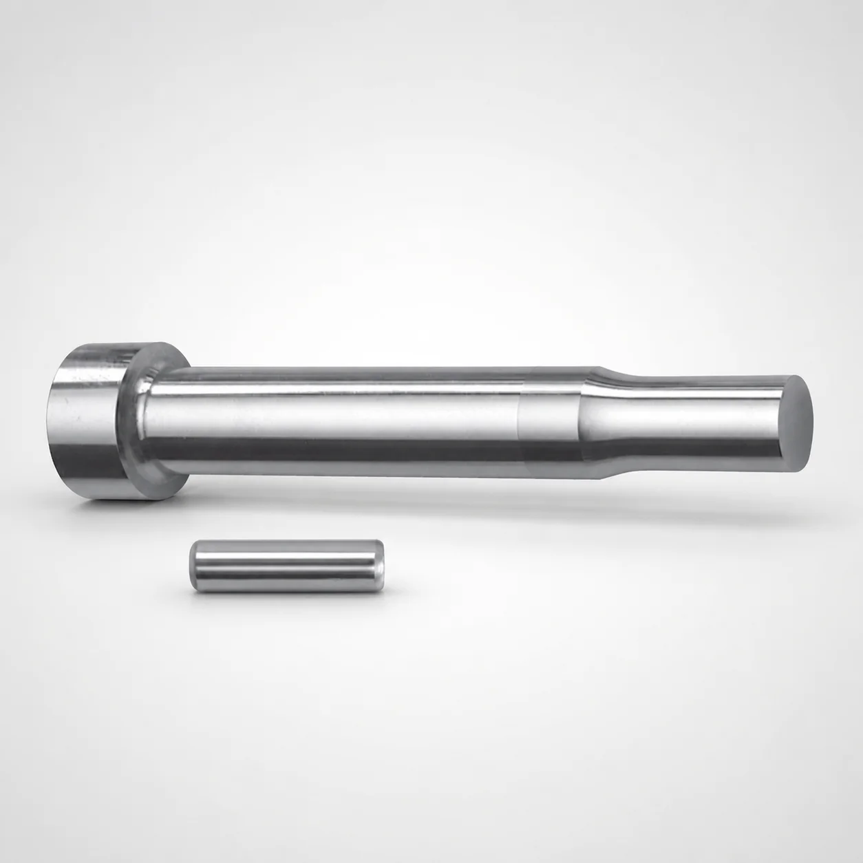
Metric XNA Coating Center Dowel Punches for Heavy Load
Center Dowel Punches for Heavy Load (Metric) (DAYTON) are engineered for stable center alignment in heavy die sets. The XNA coating supports corrosion resistance and long service performance during repeated press cycles.
- Heavy-load center locating design improves repeatable part positioning
- Built with robust tool steel and XNA coating for wear and corrosion control
- Point tip options for secure seating to match punch/receiver geometry
- Used in die sets, progressive tooling, and precision fixture locating
Specifications
164 configurations available
| Tip shape | D (Shank diameter) (mm) | L1 (Point Length) (mm) | L (Length) (mm) | P Dimension (mm) | W Dimension (mm) | R Dimension (mm) |
|---|---|---|---|---|---|---|
| H | 10 | 13 ~ 19 | 80 ~ 130 | 1.5 ~ 2.99 | 1.5 ~ 2.99 | - |
| H | 10 | 13 ~ 19 | 80 ~ 130 | 1.5 ~ 2.99 | 3 ~ 10 | - |
| H | 10 | 13 ~ 19 | 80 ~ 130 | 3 ~ 10 | 1.5 ~ 2.99 | - |
| H | 10 | 13 ~ 19 | 80 ~ 130 | 3 ~ 10 | 3 ~ 10 | - |
| H | 13 | 13 ~ 19 | 80 ~ 130 | 1.5 ~ 2.99 | 1.5 ~ 2.99 | - |
| H | 13 | 13 ~ 19 | 80 ~ 130 | 1.5 ~ 2.99 | 3 ~ 13 | - |
| H | 13 | 13 ~ 19 | 80 ~ 130 | 3 ~ 13 | 1.5 ~ 2.99 | - |
| H | 13 | 13 ~ 19 | 80 ~ 130 | 3 ~ 13 | 3 ~ 13 | - |
| H | 16 | 19 ~ 25 | 80 ~ 130 | 3 ~ 3.99 | 3 ~ 3.99 | - |
| H | 16 | 19 ~ 25 | 80 ~ 130 | 3 ~ 3.99 | 4 ~ 16 | - |
| H | 16 | 19 ~ 25 | 80 ~ 130 | 4 ~ 16 | 3 ~ 3.99 | - |
| H | 16 | 19 ~ 25 | 80 ~ 130 | 4 ~ 16 | 4 ~ 16 | - |
| H | 20 | 19 ~ 25 | 80 ~ 130 | 3 ~ 4.99 | 3 ~ 4.99 | - |
| H | 20 | 19 ~ 25 | 80 ~ 130 | 3 ~ 4.99 | 5 ~ 20 | - |
| H | 20 | 19 ~ 25 | 80 ~ 130 | 5 ~ 20 | 3 ~ 4.99 | - |
| H | 20 | 19 ~ 25 | 80 ~ 130 | 5 ~ 20 | 5 ~ 20 | - |
| H | 25 | 19 ~ 25 | 80 ~ 130 | 6 ~ 25 | 6 ~ 25 | - |
| J | 10 | 13 ~ 19 | 80 ~ 130 | 1.5 ~ 2.99 | 1.5 ~ 2.99 | - |
| J | 10 | 13 ~ 19 | 80 ~ 130 | 1.5 ~ 2.99 | 3 ~ 10 | - |
| J | 10 | 13 ~ 19 | 80 ~ 130 | 3 ~ 10 | 1.5 ~ 2.99 | - |
| J | 10 | 13 ~ 19 | 80 ~ 130 | 3 ~ 10 | 3 ~ 10 | - |
| J | 13 | 13 ~ 19 | 80 ~ 130 | 1.5 ~ 2.99 | 1.5 ~ 2.99 | - |
| J | 13 | 13 ~ 19 | 80 ~ 130 | 1.5 ~ 2.99 | 3 ~ 13 | - |
| J | 13 | 13 ~ 19 | 80 ~ 130 | 3 ~ 13 | 1.5 ~ 2.99 | - |
| J | 13 | 13 ~ 19 | 80 ~ 130 | 3 ~ 13 | 3 ~ 13 | - |
| J | 16 | 19 ~ 25 | 80 ~ 130 | 3 ~ 3.99 | 3 ~ 3.99 | - |
| J | 16 | 19 ~ 25 | 80 ~ 130 | 3 ~ 3.99 | 4 ~ 16 | - |
| J | 16 | 19 ~ 25 | 80 ~ 130 | 4 ~ 16 | 3 ~ 3.99 | - |
| J | 16 | 19 ~ 25 | 80 ~ 130 | 4 ~ 16 | 4 ~ 16 | - |
| J | 20 | 19 ~ 25 | 80 ~ 130 | 3 ~ 4.99 | 3 ~ 4.99 | - |
| J | 20 | 19 ~ 25 | 80 ~ 130 | 3 ~ 4.99 | 5 ~ 20 | - |
| J | 20 | 19 ~ 25 | 80 ~ 130 | 5 ~ 20 | 3 ~ 4.99 | - |
| J | 20 | 19 ~ 25 | 80 ~ 130 | 5 ~ 20 | 5 ~ 20 | - |
| J | 25 | 19 ~ 25 | 80 ~ 130 | 6 ~ 25 | 6 ~ 25 | - |
| K | 10 | 13 ~ 19 | 80 ~ 130 | 1.5 ~ 2.99 | 1.5 ~ 2.99 | 0.2 ~ 5 |
| K | 10 | 13 ~ 19 | 80 ~ 130 | 1.5 ~ 2.99 | 3 ~ 10 | 0.2 ~ 5 |
| K | 10 | 13 ~ 19 | 80 ~ 130 | 3 ~ 10 | 1.5 ~ 2.99 | 0.2 ~ 5 |
| K | 10 | 13 ~ 19 | 80 ~ 130 | 3 ~ 10 | 3 ~ 10 | 0.2 ~ 5 |
| K | 13 | 13 ~ 19 | 80 ~ 130 | 1.5 ~ 2.99 | 1.5 ~ 2.99 | 0.2 ~ 6.5 |
| K | 13 | 13 ~ 19 | 80 ~ 130 | 1.5 ~ 2.99 | 3 ~ 13 | 0.2 ~ 6.5 |
| K | 13 | 13 ~ 19 | 80 ~ 130 | 3 ~ 13 | 1.5 ~ 2.99 | 0.2 ~ 6.5 |
| K | 13 | 13 ~ 19 | 80 ~ 130 | 3 ~ 13 | 3 ~ 13 | 0.2 ~ 6.5 |
| K | 16 | 19 ~ 25 | 80 ~ 130 | 3 ~ 3.99 | 3 ~ 3.99 | 0.2 ~ 8 |
| K | 16 | 19 ~ 25 | 80 ~ 130 | 3 ~ 3.99 | 4 ~ 16 | 0.2 ~ 8 |
| K | 16 | 19 ~ 25 | 80 ~ 130 | 4 ~ 16 | 3 ~ 3.99 | 0.2 ~ 8 |
| K | 16 | 19 ~ 25 | 80 ~ 130 | 4 ~ 16 | 4 ~ 16 | 0.2 ~ 8 |
| K | 20 | 19 ~ 25 | 80 ~ 130 | 3 ~ 4.99 | 3 ~ 4.99 | 0.2 ~ 10 |
| K | 20 | 19 ~ 25 | 80 ~ 130 | 3 ~ 4.99 | 5 ~ 20 | 0.2 ~ 10 |
| K | 20 | 19 ~ 25 | 80 ~ 130 | 5 ~ 20 | 3 ~ 4.99 | 0.2 ~ 10 |
| K | 20 | 19 ~ 25 | 80 ~ 130 | 5 ~ 20 | 5 ~ 20 | 0.2 ~ 10 |
Product Guide
Application Scenarios+
Metric center locating dowel punches like this one are used to establish repeatable center reference in heavy-load die sets and progressive tooling. In die set applications, the punch tip engages a matching receiver/locating hole to maintain alignment across repeated press cycles, reducing drift between operations.
- Automotive & industrial progressive die sets: Use with robust receiver geometry to support stable part positioning under high tonnage. The XNA coating improves corrosion resistance for tools exposed to coolant, mist, or shop-floor humidity.
- Die set maintenance fixtures: Locating punches help technicians realign components quickly and consistently. The heavy-load design and coating support longer service life when tools are cycled during setup.
- Precision workholding/fixture locating: Select the appropriate point length and tip shape to seat securely and maintain center registration for high-accuracy forming or assembly tasks.
Material & Process Details+
The exact steel grade and hardness are not specified in the provided data, so selection should be aligned with your supplier’s tooling steel recommendation for heavy-load locating components. What is specified here is the XNA coating, which is intended to enhance corrosion resistance and improve durability at the punch/receiver interface.
- Material/coating role: The steel body provides structural rigidity for locating under load, while the XNA coating supports wear and corrosion control during repeated press cycles.
- Heat treatment state: Not specified in the provided data; confirm hardness level and treatment (e.g., quenched & tempered or similar) with the tooling documentation used for the production series.
- Wear vs. toughness trade-off: For locating punches, you typically balance surface durability at the tip with sufficient toughness to resist chipping; this is achieved through the chosen base steel and its heat treatment.
Sizing & Selection Guide+
Correct sizing for center dowel punches depends on matching the punch shank size, effective point engagement, and overall length to the mating die/fixture geometry. Start by selecting the D (shank diameter) from 10, 13, 16, 20, or 25 mm to match the receiver hole/bore size in your base plate or die set.
- Overall length (L): Fixed at 80–130 mm. Choose the length that ensures full seating without bottoming against the base or damaging the receiver.
- Point length (L1): Select the required engagement from 13–19 mm or 19–25 mm to achieve stable center location.
- Tip shape: Choose the appropriate H, J, K, L, N, O, R, V, X, Y, or Z to match your punch/receiver seating geometry.
- Tolerance/fit: Use your standard die clearance for locating pins/punches; if receiver bores are precision-ground, keep assembly variation controlled to preserve repeatability. Dimensions D and L1/L are functional drivers; P, W, and R should be matched to the detailed drawing spec for the selected series.
Frequently Asked Questions
Which shank diameter (D) options are available for this metric heavy-load center dowel punch series?+
The available D (shank diameter) values are 10, 13, 16, 20, and 25 mm. Select D to match the mating receiver hole/bore in the die set or fixture so the locating interface supports repeatable center registration.
How do I choose the point length (L1) to ensure proper seating without bottoming in the receiver?+
This series provides L1 in two ranges: 13–19 mm and 19–25 mm. Match L1 to the available depth of engagement in the receiver to ensure the tip seats securely while avoiding hard bottoming that can damage locating surfaces.
What tip shapes are supported, and how should I select one for my punch/receiver geometry?+
Supported tip shapes are H, J, K, L, N, O, R, V, X, Y, and Z. Choose the tip shape based on your specific receiver geometry and seating requirement so the punch tip forms a stable locating interface under heavy-load cycling.
Does the XNA coating primarily target corrosion resistance or also affect wear at the locating interface?+
The provided description specifies that XNA coating supports corrosion resistance and long service performance during repeated press cycles. Because the coating is applied to the locating punch, it is used to protect the punch/receiver interface where wear and environmental exposure can occur.
Which dimensional parameters besides D and L1 should I verify against my die receiver drawing?+
Besides D and L1, verify series-controlled interface parameters such as P (1.5–18 mm), W (1.5–6 mm), and the R radius options (0.2–5, 0.2–6.5, 0.2–8, 0.2–10, 0.2–12.5). Also confirm the fixed overall length L (80–130 mm) so the punch does not interfere with the base plate or ejector system.
Related Products

Metric Dowel Punches for Heavy Load with Single-Stepped Shank (M5)

Metric Center Dowel Punches for Heavy Load TiCN Coated

JIS Standard SKH51 Steel Ejector Punches for Heavy Load with Dowel Holes

SKH51 Steel TiCN Coating Ejector Punches for Heavy Load with Dowel Holes

RW Coated Dowel Punches for Heavy Load - Single-Stepped Shank

Center Dowel Ejector Punches for Heavy Load (RW Coating) - SKH51 Steel
Need Custom Specifications?
Our engineering team can help with custom configurations, material selection, and volume pricing.