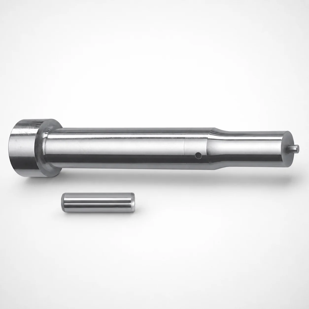
Center Dowel Punches for Heavy Load - Metric
Center Dowel Punches for Heavy Load - Metric by DAYTON provide stable center locating for heavy-duty mold and die setups, improving part-to-die registration repeatability in production. The metric, ejector-style punch design supports long service cycles under demanding forming conditions.
- Designed for center alignment in heavy-load die systems
- Metric punch body supports multiple shank diameters and lengths
- Available tip geometries (X, R, K, O, H, L, J, N, V, Y, Z) for mating features
- Configurable point length and profile dimensions for precise locating
Specifications
112 configurations available
| Tip shape | D (Shank diameter) (mm) | Jektole group | L1 (Point Length) (mm) | L (Length) (mm) | P Dimension (mm) | W Dimension (mm) | R Dimension (mm) |
|---|---|---|---|---|---|---|---|
| H | 10 | J6M | 13 ~ 19 | 80 ~ 130 | 4 ~ 4.99 | 4 ~ 4.99 | - |
| H | 10 | J6M | 13 ~ 19 | 80 ~ 130 | 4 ~ 4.99 | 5 ~ 10 | - |
| H | 10 | J6M | 13 ~ 19 | 80 ~ 130 | 5 ~ 10 | 4 ~ 4.99 | - |
| H | 10 | J6M | 13 ~ 19 | 80 ~ 130 | 5 ~ 10 | 5 ~ 10 | - |
| H | 13 | J6M | 13 ~ 19 | 80 ~ 130 | 4 ~ 5.99 | 4 ~ 5.99 | - |
| H | 13 | J6M | 13 ~ 19 | 80 ~ 130 | 4 ~ 5.99 | 6 ~ 13 | - |
| H | 13 | J6M | 13 ~ 19 | 80 ~ 130 | 6 ~ 13 | 4 ~ 5.99 | - |
| H | 13 | J6M | 13 ~ 19 | 80 ~ 130 | 6 ~ 13 | 6 ~ 13 | - |
| H | 16 | J9M | 19 ~ 25 | 80 ~ 130 | 6 ~ 16 | 6 ~ 16 | - |
| H | 20 | J9M | 19 ~ 25 | 80 ~ 130 | 6 ~ 20 | 6 ~ 20 | - |
| H | 25 | J9M | 19 ~ 25 | 80 ~ 130 | 6 ~ 25 | 6 ~ 25 | - |
| J | 10 | J6M | 13 ~ 19 | 80 ~ 130 | 4 ~ 4.99 | 4 ~ 4.99 | - |
| J | 10 | J6M | 13 ~ 19 | 80 ~ 130 | 4 ~ 4.99 | 5 ~ 10 | - |
| J | 10 | J6M | 13 ~ 19 | 80 ~ 130 | 5 ~ 10 | 4 ~ 4.99 | - |
| J | 10 | J6M | 13 ~ 19 | 80 ~ 130 | 5 ~ 10 | 5 ~ 10 | - |
| J | 13 | J6M | 13 ~ 19 | 80 ~ 130 | 4 ~ 5.99 | 4 ~ 5.99 | - |
| J | 13 | J6M | 13 ~ 19 | 80 ~ 130 | 4 ~ 5.99 | 6 ~ 13 | - |
| J | 13 | J6M | 13 ~ 19 | 80 ~ 130 | 6 ~ 13 | 4 ~ 5.99 | - |
| J | 13 | J6M | 13 ~ 19 | 80 ~ 130 | 6 ~ 13 | 6 ~ 13 | - |
| J | 16 | J9M | 19 ~ 25 | 80 ~ 130 | 6 ~ 16 | 6 ~ 16 | - |
| J | 20 | J9M | 19 ~ 25 | 80 ~ 130 | 6 ~ 20 | 6 ~ 20 | - |
| J | 25 | J9M | 19 ~ 25 | 80 ~ 130 | 6 ~ 25 | 6 ~ 25 | - |
| K | 10 | J6M | 13 ~ 19 | 80 ~ 130 | 4 ~ 4.99 | 4 ~ 4.99 | 0.2 ~ 5 |
| K | 10 | J6M | 13 ~ 19 | 80 ~ 130 | 4 ~ 4.99 | 5 ~ 10 | 0.2 ~ 5 |
| K | 10 | J6M | 13 ~ 19 | 80 ~ 130 | 5 ~ 10 | 4 ~ 4.99 | 0.2 ~ 5 |
| K | 10 | J6M | 13 ~ 19 | 80 ~ 130 | 5 ~ 10 | 5 ~ 10 | 0.2 ~ 5 |
| K | 13 | J6M | 13 ~ 19 | 80 ~ 130 | 4 ~ 5.99 | 4 ~ 5.99 | 0.2 ~ 6.5 |
| K | 13 | J6M | 13 ~ 19 | 80 ~ 130 | 4 ~ 5.99 | 6 ~ 13 | 0.2 ~ 6.5 |
| K | 13 | J6M | 13 ~ 19 | 80 ~ 130 | 6 ~ 13 | 4 ~ 5.99 | 0.2 ~ 6.5 |
| K | 13 | J6M | 13 ~ 19 | 80 ~ 130 | 6 ~ 13 | 6 ~ 13 | 0.2 ~ 6.5 |
| K | 16 | J9M | 19 ~ 25 | 80 ~ 130 | 6 ~ 16 | 6 ~ 16 | 0.2 ~ 8 |
| K | 20 | J9M | 19 ~ 25 | 80 ~ 130 | 6 ~ 20 | 6 ~ 20 | 0.2 ~ 10 |
| K | 25 | J9M | 19 ~ 25 | 80 ~ 130 | 6 ~ 25 | 6 ~ 25 | 0.2 ~ 12.5 |
| L | 10 | J6M | 13 ~ 19 | 80 ~ 130 | 4 ~ 4.99 | 4 ~ 4.99 | - |
| L | 10 | J6M | 13 ~ 19 | 80 ~ 130 | 4 ~ 4.99 | 5 ~ 10 | - |
| L | 10 | J6M | 13 ~ 19 | 80 ~ 130 | 5 ~ 10 | 4 ~ 4.99 | - |
| L | 10 | J6M | 13 ~ 19 | 80 ~ 130 | 5 ~ 10 | 5 ~ 10 | - |
| L | 13 | J6M | 13 ~ 19 | 80 ~ 130 | 4 ~ 5.99 | 4 ~ 5.99 | - |
| L | 13 | J6M | 13 ~ 19 | 80 ~ 130 | 4 ~ 5.99 | 6 ~ 13 | - |
| L | 13 | J6M | 13 ~ 19 | 80 ~ 130 | 6 ~ 13 | 4 ~ 5.99 | - |
| L | 13 | J6M | 13 ~ 19 | 80 ~ 130 | 6 ~ 13 | 6 ~ 13 | - |
| L | 16 | J9M | 19 ~ 25 | 80 ~ 130 | 6 ~ 16 | 6 ~ 16 | - |
| L | 20 | J9M | 19 ~ 25 | 80 ~ 130 | 6 ~ 20 | 6 ~ 20 | - |
| L | 25 | J9M | 19 ~ 25 | 80 ~ 130 | 6 ~ 25 | 6 ~ 25 | - |
| N | 10 | J6M | 13 ~ 19 | 80 ~ 130 | - | 4 ~ 4.99 | - |
| N | 10 | J6M | 13 ~ 19 | 80 ~ 130 | - | 5 ~ 10 | - |
| N | 13 | J6M | 13 ~ 19 | 80 ~ 130 | - | 4 ~ 5.99 | - |
| N | 13 | J6M | 13 ~ 19 | 80 ~ 130 | - | 6 ~ 13 | - |
| N | 16 | J9M | 19 ~ 25 | 80 ~ 130 | - | 6 ~ 16 | - |
| N | 20 | J9M | 19 ~ 25 | 80 ~ 130 | - | 6 ~ 20 | - |
Product Guide
Application Scenarios+
Center dowel punches like this heavy-load metric variant are used in the die set to establish reliable center alignment during repeat production cycles. They are particularly effective where registration accuracy directly impacts downstream forming or casting features and where misalignment can cause tool wear or part defects.
- Automotive die casting & stamping: Use the punch in the bolster/die receiver interface to improve part-to-die registration repeatability, especially when the forming load is high and the tooling experiences frequent cycles.
- Heavy-load progressive forming: Pair with matching cavities/locating features to maintain positional stability across multiple stations; the available tip geometries support mating with different alignment recesses or pilot profiles.
- Industrial appliance housings: For housings requiring consistent concentricity and feature alignment, select the point length and profile-related parameters to stabilize locating under demanding die conditions.
The metric, ejector-style configuration with multiple shank diameters (10–25 mm) and point lengths (13–19 mm, 19–25 mm) makes it suited for heavy-duty die systems where stable center location is required.
Material & Process Details+
The provided metadata does not specify the exact steel grade, hardness (HRC), or heat treatment state for this DAYTON center dowel punch series. Because key wear and toughness performance is strongly tied to the steel and heat treatment, those details should be confirmed from the product datasheet or material certificate for final engineering qualification.
What you can control from the configuration data:
- Tip and profile-related dimensions (tip shape, P, W, and R ranges) to tune contact mechanics and locating repeatability.
- Point length (L1) selection (13–19 mm or 19–25 mm) to manage lever effects under load.
- Shaft diameter (D) selection (10, 13, 16, 20, 25 mm) to balance rigidity versus packaging constraints.
In general, harder tool steels improve wear resistance, while tougher states (tempered structures) can reduce chipping risk at high contact stress; verify the actual spec for the selected configuration.
Sizing & Selection Guide+
Select the punch dimensions by matching the shank diameter, overall length, and point geometry to the corresponding locating feature in your die set. This series supports D = 10, 13, 16, 20, or 25 mm with a fixed L = 80–130 mm, plus selectable point length (L1) ranges of 13–19 mm or 19–25 mm.
- Match D: Choose the shank diameter that fits the die block/bushing bore. Confirm any press-fit or sliding-fit requirements with your receiving-hole tolerance stack.
- Set L (fixed): Ensure the 80–130 mm length provides correct engagement depth and clearance for ejector/locating movement in your tooling layout.
- Match tip geometry: Select the tip shape (H, J, K, L, N, O, R, V, X, Y, Z) and align contact parameters P (4–18 mm), W (4–6 mm), and R (0.2–5, 0.2–6.5, 0.2–8, 0.2–10, 0.2–12.5 mm) to the mating feature.
If your design uses close tolerance locating, request the configured tolerance/fit data for the selected tip shape and R range; the metadata provides dimension ranges, not tolerance class.
Frequently Asked Questions
How do I choose the correct shank diameter (D) for heavy-load die alignment with this metric dowel punch?+
This series offers D = 10, 13, 16, 20, or 25 mm. Select the diameter that matches the receiving bore/bushing in your die set with the required fit (sliding or press-fit), considering your tolerance stack-up. If the bore tolerances are tight, verify the provided tolerance class for the specific configuration before machining or rework.
What should I use to select the point length (L1) when the die requires deeper or shorter locating engagement?+
Point length L1 is available in two ranges: 13–19 mm or 19–25 mm. Choose the longer range when you need increased engagement depth to improve locating stability, and the shorter range when packaging or clearance limits reduce allowable engagement. Confirm that the selected L1 does not interfere with adjacent tooling surfaces during cycling.
How do the tip shapes (H, J, K, L, N, O, R, V, X, Y, Z) affect mating with the locating recess or pilot feature?+
Tip shapes determine how the locating surface contacts the mating die feature. Use the tip shape that matches your receiver geometry and then fine-tune with the configured profile dimensions: P (4–18 mm), W (4–6 mm), and R (0.2–5 to 0.2–12.5 mm, depending on the option). This ensures consistent centering and repeatable contact under heavy loads.
The series lists P, W, and R ranges—how should I map these to my CAD model for the locating feature?+
In your CAD, align the receiver feature dimensions to the punch’s configured parameters: P (4–18 mm) for the specified profile dimension, W (4–6 mm) for width-related geometry, and R for radius/contact transitions (options include 0.2–5, 0.2–6.5, 0.2–8, 0.2–10, 0.2–12.5 mm). Use the exact configured values corresponding to the selected tip shape. If you only model mid-range values, you may end up with poor contact or reduced centering repeatability.
What overall punch length (L) options are available and how do they influence tool layout clearance?+
The fixed overall length L is listed as 80–130 mm. Select a length that provides the required functional engagement without exceeding available space in the die set. When changing L, re-check clearances for movement paths and any nearby components to avoid interference during assembly and cycling.
Related Products

Metric Dowel Punches for Heavy Load with Single-Stepped Shank (M5)

Metric Center Dowel Punches for Heavy Load TiCN Coated

JIS Standard SKH51 Steel Ejector Punches for Heavy Load with Dowel Holes

SKH51 Steel TiCN Coating Ejector Punches for Heavy Load with Dowel Holes

RW Coated Dowel Punches for Heavy Load - Single-Stepped Shank

Center Dowel Ejector Punches for Heavy Load (RW Coating) - SKH51 Steel
Need Custom Specifications?
Our engineering team can help with custom configurations, material selection, and volume pricing.