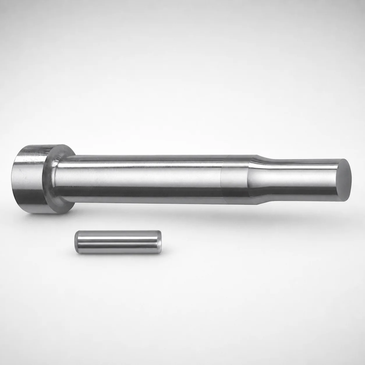
Center Dowel Punches for Heavy Load - Metric CRN Coating
Center Dowel Punches for Heavy Load - Metric (CRN coating) provide reliable centering force for die and mold assemblies, helping maintain alignment under heavy production loads. Engineered for repeatable positioning and smooth installation in metric tool layouts.
- Heavy-load center dowel punch geometry supports accurate dowel hole alignment
- CRN coating improves wear resistance for longer service intervals
- Optimized hardened punch form for consistent fit during high-cycle operations
- Metric configuration suited to punch tooling and die base alignment tasks
Specifications
164 configurations available
| Tip shape | D (Shank diameter) (mm) | L1 (Point Length) (mm) | L (Length) (mm) | P Dimension (mm) | W Dimension (mm) | R Dimension (mm) |
|---|---|---|---|---|---|---|
| H | 10 | 13 ~ 19 | 80 ~ 130 | 1.5 ~ 2.99 | 1.5 ~ 2.99 | - |
| H | 10 | 13 ~ 19 | 80 ~ 130 | 1.5 ~ 2.99 | 3 ~ 10 | - |
| H | 10 | 13 ~ 19 | 80 ~ 130 | 3 ~ 10 | 1.5 ~ 2.99 | - |
| H | 10 | 13 ~ 19 | 80 ~ 130 | 3 ~ 10 | 3 ~ 10 | - |
| H | 13 | 13 ~ 19 | 80 ~ 130 | 1.5 ~ 2.99 | 1.5 ~ 2.99 | - |
| H | 13 | 13 ~ 19 | 80 ~ 130 | 1.5 ~ 2.99 | 3 ~ 13 | - |
| H | 13 | 13 ~ 19 | 80 ~ 130 | 3 ~ 13 | 1.5 ~ 2.99 | - |
| H | 13 | 13 ~ 19 | 80 ~ 130 | 3 ~ 13 | 3 ~ 13 | - |
| H | 16 | 19 ~ 25 | 80 ~ 130 | 3 ~ 3.99 | 3 ~ 3.99 | - |
| H | 16 | 19 ~ 25 | 80 ~ 130 | 3 ~ 3.99 | 4 ~ 16 | - |
| H | 16 | 19 ~ 25 | 80 ~ 130 | 4 ~ 16 | 3 ~ 3.99 | - |
| H | 16 | 19 ~ 25 | 80 ~ 130 | 4 ~ 16 | 4 ~ 16 | - |
| H | 20 | 19 ~ 25 | 80 ~ 130 | 3 ~ 4.99 | 3 ~ 4.99 | - |
| H | 20 | 19 ~ 25 | 80 ~ 130 | 3 ~ 4.99 | 5 ~ 20 | - |
| H | 20 | 19 ~ 25 | 80 ~ 130 | 5 ~ 20 | 3 ~ 4.99 | - |
| H | 20 | 19 ~ 25 | 80 ~ 130 | 5 ~ 20 | 5 ~ 20 | - |
| H | 25 | 19 ~ 25 | 80 ~ 130 | 6 ~ 25 | 6 ~ 25 | - |
| J | 10 | 13 ~ 19 | 80 ~ 130 | 1.5 ~ 2.99 | 1.5 ~ 2.99 | - |
| J | 10 | 13 ~ 19 | 80 ~ 130 | 1.5 ~ 2.99 | 3 ~ 10 | - |
| J | 10 | 13 ~ 19 | 80 ~ 130 | 3 ~ 10 | 1.5 ~ 2.99 | - |
| J | 10 | 13 ~ 19 | 80 ~ 130 | 3 ~ 10 | 3 ~ 10 | - |
| J | 13 | 13 ~ 19 | 80 ~ 130 | 1.5 ~ 2.99 | 1.5 ~ 2.99 | - |
| J | 13 | 13 ~ 19 | 80 ~ 130 | 1.5 ~ 2.99 | 3 ~ 13 | - |
| J | 13 | 13 ~ 19 | 80 ~ 130 | 3 ~ 13 | 1.5 ~ 2.99 | - |
| J | 13 | 13 ~ 19 | 80 ~ 130 | 3 ~ 13 | 3 ~ 13 | - |
| J | 16 | 19 ~ 25 | 80 ~ 130 | 3 ~ 3.99 | 3 ~ 3.99 | - |
| J | 16 | 19 ~ 25 | 80 ~ 130 | 3 ~ 3.99 | 4 ~ 16 | - |
| J | 16 | 19 ~ 25 | 80 ~ 130 | 4 ~ 16 | 3 ~ 3.99 | - |
| J | 16 | 19 ~ 25 | 80 ~ 130 | 4 ~ 16 | 4 ~ 16 | - |
| J | 20 | 19 ~ 25 | 80 ~ 130 | 3 ~ 4.99 | 3 ~ 4.99 | - |
| J | 20 | 19 ~ 25 | 80 ~ 130 | 3 ~ 4.99 | 5 ~ 20 | - |
| J | 20 | 19 ~ 25 | 80 ~ 130 | 5 ~ 20 | 3 ~ 4.99 | - |
| J | 20 | 19 ~ 25 | 80 ~ 130 | 5 ~ 20 | 5 ~ 20 | - |
| J | 25 | 19 ~ 25 | 80 ~ 130 | 6 ~ 25 | 6 ~ 25 | - |
| K | 10 | 13 ~ 19 | 80 ~ 130 | 1.5 ~ 2.99 | 1.5 ~ 2.99 | 0.2 ~ 5 |
| K | 10 | 13 ~ 19 | 80 ~ 130 | 1.5 ~ 2.99 | 3 ~ 10 | 0.2 ~ 5 |
| K | 10 | 13 ~ 19 | 80 ~ 130 | 3 ~ 10 | 1.5 ~ 2.99 | 0.2 ~ 5 |
| K | 10 | 13 ~ 19 | 80 ~ 130 | 3 ~ 10 | 3 ~ 10 | 0.2 ~ 5 |
| K | 13 | 13 ~ 19 | 80 ~ 130 | 1.5 ~ 2.99 | 1.5 ~ 2.99 | 0.2 ~ 6.5 |
| K | 13 | 13 ~ 19 | 80 ~ 130 | 1.5 ~ 2.99 | 3 ~ 13 | 0.2 ~ 6.5 |
| K | 13 | 13 ~ 19 | 80 ~ 130 | 3 ~ 13 | 1.5 ~ 2.99 | 0.2 ~ 6.5 |
| K | 13 | 13 ~ 19 | 80 ~ 130 | 3 ~ 13 | 3 ~ 13 | 0.2 ~ 6.5 |
| K | 16 | 19 ~ 25 | 80 ~ 130 | 3 ~ 3.99 | 3 ~ 3.99 | 0.2 ~ 8 |
| K | 16 | 19 ~ 25 | 80 ~ 130 | 3 ~ 3.99 | 4 ~ 16 | 0.2 ~ 8 |
| K | 16 | 19 ~ 25 | 80 ~ 130 | 4 ~ 16 | 3 ~ 3.99 | 0.2 ~ 8 |
| K | 16 | 19 ~ 25 | 80 ~ 130 | 4 ~ 16 | 4 ~ 16 | 0.2 ~ 8 |
| K | 20 | 19 ~ 25 | 80 ~ 130 | 3 ~ 4.99 | 3 ~ 4.99 | 0.2 ~ 10 |
| K | 20 | 19 ~ 25 | 80 ~ 130 | 3 ~ 4.99 | 5 ~ 20 | 0.2 ~ 10 |
| K | 20 | 19 ~ 25 | 80 ~ 130 | 5 ~ 20 | 3 ~ 4.99 | 0.2 ~ 10 |
| K | 20 | 19 ~ 25 | 80 ~ 130 | 5 ~ 20 | 5 ~ 20 | 0.2 ~ 10 |
Product Guide
Application Scenarios+
This heavy-load center dowel punch is used to establish and verify dowel hole alignment in die and mold assemblies, especially where repeated clamp cycles can shift tool components. In automotive connector and terminal tooling, the metric shank sizes (e.g., D = 10 to 25 mm) help maintain stable registration between the die set halves and locating bushings during high-cycle production.
In appliance housings and thin-wall plastic injection molds, accurate center positioning reduces part-to-part variation by keeping the core and cavity alignment consistent during startup and thermal expansion. The CRN coating supports longer wear life at the punch-to-hole interface, which is critical during frequent build/repair cycles.
It is also suitable for general die bases and progressive stamping tooling where heavy mechanical loads demand reliable centering force and repeatable fit. Select the appropriate tip shape and point length to match the lead-in requirements of your metric locating system for smooth installation and predictable engagement.
Material & Process Details+
The input data specifies a CRN coating on a hardened center dowel punch intended for stable alignment under heavy production loads. While the exact steel grade is not provided in the specifications, the design targets high surface durability at the contact zone for improved wear resistance.
- Coating role (CRN): enhances resistance to abrasion and fretting at the punch point during repeated alignment cycles.
- Heat-treatment state: described as an “optimized hardened punch form,” indicating a hardened condition for consistent fit under high-cycle operation.
- Trade-off: hardening increases wear resistance and centering stability, but may require careful alignment and proper hole prep to avoid edge chipping under shock loads.
If you need confirmed metallurgy (exact grade and HRC), request the heat-treatment report for the 250301835132 series, since multiple hardened grades may be used depending on tip geometry and diameter.
Sizing & Selection Guide+
Use the provided metric dimensions to match the center dowel punch to your mold base and locating hole system. Start with the required D (shank diameter): choose 10, 13, 16, 20, or 25 mm to correspond to the dowel hole/bushing size in the die or mold halves.
Select the L (length) based on the available tool thickness and how much engagement you need; this series lists L = 80 to 130 mm. Then choose the L1 (point length) from 13–19 mm or 19–25 mm to ensure the lead-in reaches full alignment without bottoming out.
- Configure the Tip shape (H, J, K, L, N, O, R, V, X, Y, Z) to match your hole-entry chamfer/lead design and expected alignment path.
- Match P (1.5–18 mm), W (1.5–6 mm), and R (0.2–5, 0.2–6.5, 0.2–8, 0.2–10, 0.2–12.5 mm) to the geometry of your locating feature.
Since tolerances are not listed, verify your drawing-driven clearance/interference with the receiving dowel holes; for heavy-load builds, consistent engagement typically requires controlled hole finishes and straightness.
Frequently Asked Questions
Which shank diameter range (D) is available for this series, and how do I choose the correct one for my dowel holes?+
How should I select point length (L1) and overall length (L) for proper engagement during mold assembly?+
What tip shapes are supported, and when would I pick a different tip shape for alignment stability?+
What is the role of the CRN coating in heavy-load die and mold builds?+
How do the P, W, and R geometry parameters affect compatibility with locating features?+
Related Products

Metric Dowel Punches for Heavy Load with Single-Stepped Shank (M5)

Metric Center Dowel Punches for Heavy Load TiCN Coated

JIS Standard SKH51 Steel Ejector Punches for Heavy Load with Dowel Holes

SKH51 Steel TiCN Coating Ejector Punches for Heavy Load with Dowel Holes

RW Coated Dowel Punches for Heavy Load - Single-Stepped Shank

Center Dowel Ejector Punches for Heavy Load (RW Coating) - SKH51 Steel
Need Custom Specifications?
Our engineering team can help with custom configurations, material selection, and volume pricing.