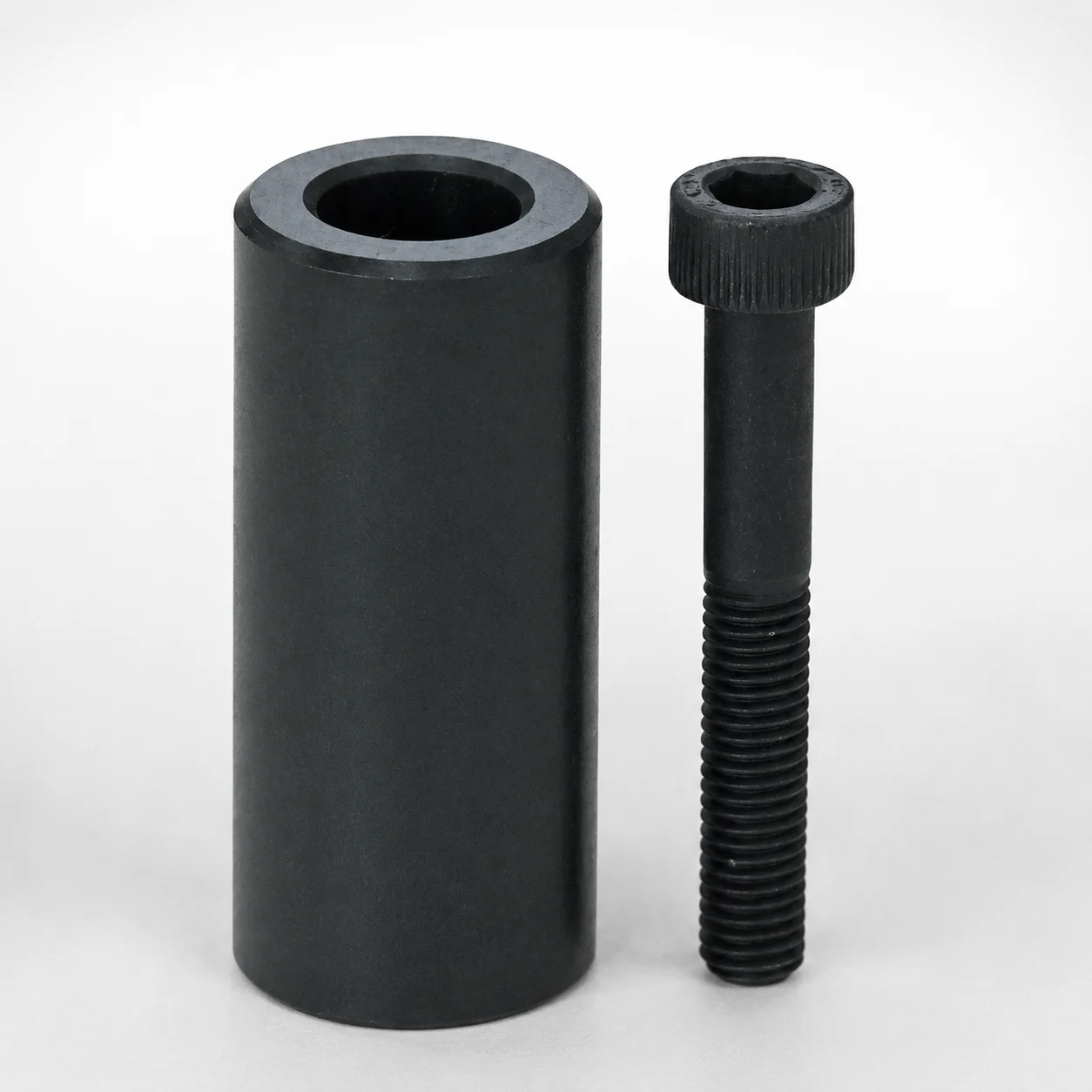
DS Type Distance Spacers - Counterbore Cylinders with Bolts
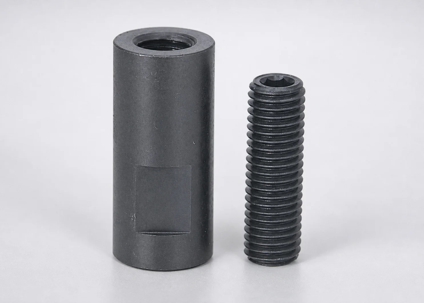
DS Type distance spacers - counterbore cylinders with bolts are designed to set and maintain accurate tool-to-tool spacing in mold and automation assemblies. The counterbore cylinder body with bolts supports secure, repeatable positioning.
- DS type spacer design delivers consistent spacing for assembly control
- Counterbore cylinder form provides reliable bolt engagement and alignment
- Spacer length suited for line-stop setups where stable stack height matters
- Commonly used in plastic mold and tooling distance adjustments
Specifications
7 configurations available
| D (Outer diameter) (mm) | type |
|---|---|
| 19 | - |
| 20 | - |
| 24 | - |
| 25 | - |
| 29 | - |
| 32 | - |
| 38 | - |
Product Guide
Application Scenarios+
DS type distance spacers with counterbore cylinders and bolts are used inside injection mold tooling stacks to control tool-to-tool spacing between plates, supports, or line-stop related components. They fit where precise stack height repeatability is required, such as during setup, maintenance, and changeovers.
- Automotive and consumer parts mold assemblies: use these spacers to maintain consistent cavity/leader alignment and steady shut-off clearances across repeated press cycles.
- Multi-station automation and transfer tooling: the counterbore cylinder with bolts helps lock the spacer position, reducing slip risk when external loads affect stacked components.
- Precision line-stop / stop-block configurations: the spacer length supports stable stack height so the tooling surfaces land within the intended separation.
The counterbore cylinder body with bolt mounting is particularly suited for these applications because it provides secure, repeatable positioning while supporting accurate spacing control in plastic mold and tooling distance adjustments.
Material & Process Details+
The provided specifications for this DS type distance spacer define dimensional parameters (e.g., D = 19 ~ 38 mm) and mounting form, but do not list a specific steel grade, hardness (HRC), or heat treatment condition in the input data.
For selection in mold bases and auxiliary tooling, engineers typically verify compatibility with the surrounding hardware (e.g., plate steels and bolt standards) and confirm whether the spacer is delivered pre-hardened or requires post-processing to meet wear and load expectations.
- What to confirm: steel grade, heat treatment state (quenched & tempered, nitrided, etc.), and target hardness for wear resistance under clamping loads.
- Trade-off expectation: higher hardness generally improves wear resistance but can reduce toughness if not balanced for the assembly load profile.
If you share the material grade or drawings for this series, the hardness and heat-treatment specifics can be stated precisely.
Sizing & Selection Guide+
Select the correct spacer by matching the spacer outer diameter D to the available clearance and locating surfaces in your tooling stack. For this series, D is specified as 19 ~ 38 mm, so choose a diameter that fits the intended recesses/bore openings without interference.
- Match to cavity/core or plate layout: confirm the counterbore and bolt positions in the neighboring components so the spacer does not shift under clamping.
- Maintain stack height: use the spacer’s length (from the specific SKU/drawing, if available) to achieve the required tool-to-tool separation for line-stop or spacing adjustments.
- Tolerance and fit: target a fit that prevents play during cycling; if nearby parts specify tight fits, ensure the spacer’s OD and bolt features are within those assembly tolerances.
Dimensions are typically fixed per ordered variant; only choose among the available OD range (19–38 mm) rather than expecting on-site adjustability.
Frequently Asked Questions
How do I choose the correct OD (D) value for DS type distance spacers in my tooling stack?+
For this series, the outer diameter is specified as D = 19 ~ 38 mm. Select the variant whose OD matches the clearance and locating feature dimensions in the adjacent plates so the spacer can sit concentrically without interference.
Also verify that the counterbore cylinder and bolt engagement areas align with the mating component’s bolt pattern to avoid mispositioning during clamping.
When should I use counterbore cylinder with bolts instead of a simple spacer in plastic mold assemblies?+
Use the counterbore cylinder with bolts when you need secure, repeatable positioning under press loads or during frequent setup changes. The bolt-mounted counterbore design helps reduce the risk of spacer drift compared with friction-only stack designs.
This is especially relevant for line-stop or multi-part tooling stacks where stable spacing is critical.
What stack-height considerations apply to DS type distance spacers used for line-stop setups?+
DS type distance spacers are intended to maintain accurate tool-to-tool spacing and therefore stack height stability. In line-stop configurations, select the ordered spacer length (from the exact SKU/drawing for the series) so the tooling surfaces meet the required separation.
Confirm that the bolt/counterbore arrangement does not introduce clearance variation when the tooling is tightened.
What fit and tolerance should I target around the spacer outer diameter (D) to prevent play?+
The provided specification gives the available OD range (D = 19 ~ 38 mm), but the exact tolerance is not included in the input data. In design, match the spacer OD to the surrounding bore/recess clearances so that there is no lateral play during cycling.
If adjacent components specify a fit class (e.g., H7/g6 type fits), ensure the spacer variant and hardware are compatible with those tolerances.
Do DS type counterbore cylinder spacers require any specific material/heat-treatment confirmation for wear and toughness?+
The input data does not specify a steel grade, hardness (HRC), or heat-treatment state for this series, so those details must be confirmed from the product documentation. For high-cycle tooling stacks, verify whether the spacer is delivered pre-hardened or requires coating/processing.
Hardness affects wear resistance, while toughness impacts resistance to cracking under repeated clamping loads—confirm both for your assembly’s load profile.
Related Products

Need Custom Specifications?
Our engineering team can help with custom configurations, material selection, and volume pricing.