Components for Large Mold
Guiding, ejection, and venting components engineered for injection molds exceeding 800 × 800 mm. Bolt-fixing retention, oversized diameters, and configurable lengths for industrial-scale tooling.
Products
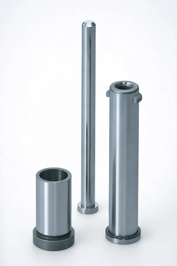
Rectangular Ejector Pins
M2 and H13 blade-type ejector pins for narrow rib and slot ejection in large molds. JIS and 8mm head heights, standard and R-chamfered profiles.
11 Series →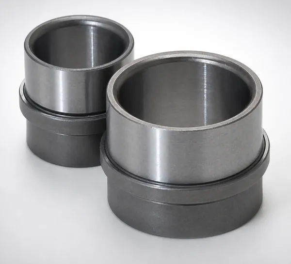
Ejector Leader Pins
Precision guide pins for ejector plate alignment. Both-ends-stepped and bolt-fixing counterbore variants for medium to large molds.
2 Series →
Return Pins
Mechanical return mechanism for ejector plate retraction. Counterbore head and tapped-both-ends variants with 8mm head thickness.
2 Series →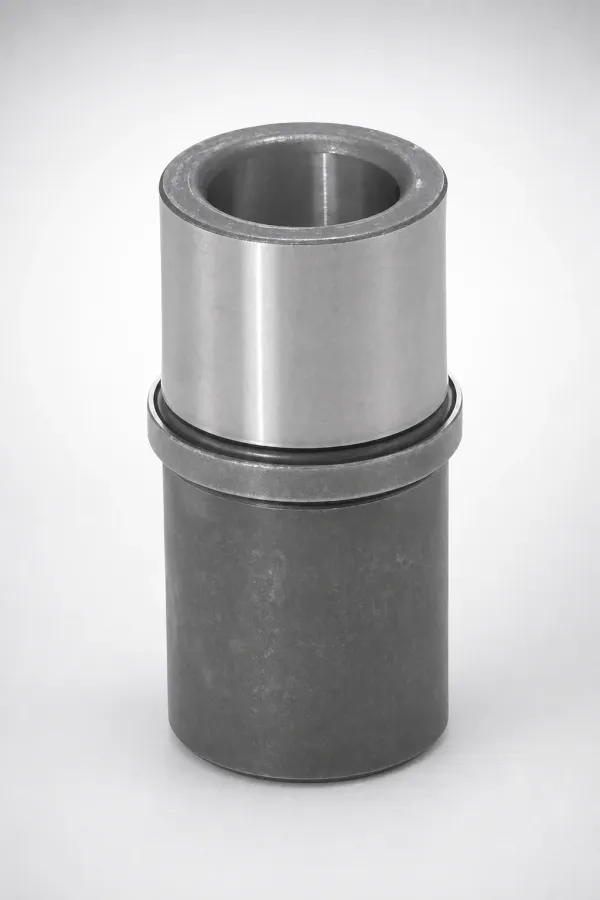
Leader Pins
Bolt-fixing leader pins for mold plate alignment. Straight, guiding-assist, and configurable-length variants for medium to large molds.
3 Series →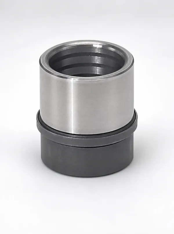
Leader Bushings
Oil-groove leader bushings for large mold guiding systems. Straight type with lubrication channels for extended maintenance intervals.
1 Series →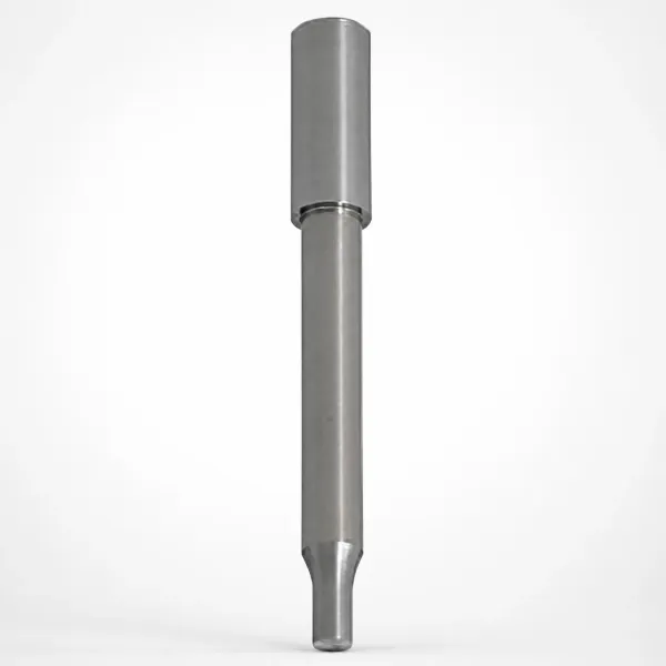
Stopper Plates for Leader Bushings
Retention plates preventing leader bushing axial migration in large molds under thermal cycling and high clamp force.
1 Series →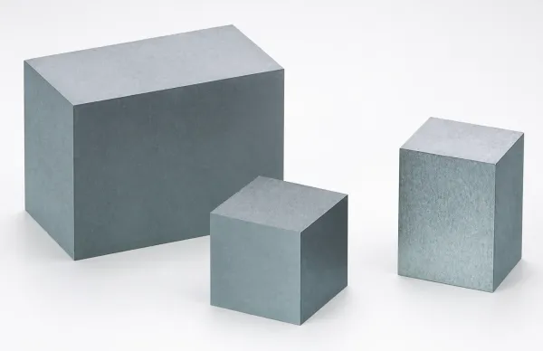
Cavity Inserts for Gas Vent
1049 steel gas venting inserts for large mold cavities. Controlled porosity allows air evacuation while blocking resin flash.
1 Series →Component Selection Overview
| Component | Function | Material | Key Specification |
|---|---|---|---|
| Rectangular Ejector Pins | Eject narrow ribs and slots | M2 or H13 nitrided | Blade width × thickness, configurable |
| Ejector Leader Pins | Guide ejector plate alignment | Case-hardened steel | Ø20–Ø50 mm, bolt-fixed |
| Return Pins | Retract ejector plate before mold close | Through-hardened steel | Ø16–Ø40 mm, 8mm head |
| Leader Pins | Align mold halves during close | Case-hardened steel | Ø40–Ø80 mm, bolt-fixed |
| Leader Bushings | Receive leader pins with controlled clearance | Bronze or steel | Oil grooves for lubrication |
| Stopper Plates | Prevent bushing axial movement | 1045 steel | Matched to bushing OD |
| Cavity Inserts (Gas Vent) | Evacuate air without flash | 1049 porous steel | Controlled porosity |
Decision rule: Start with the comparison table to identify which component categories your mold design requires, then drill into each category for detailed specifications. For detailed guidance, see our Large Mold vs Standard Mold Components — What Changes Above 800mm?.
What Problem Are You Solving?
Mold Plate Alignment (Guiding)
Misalignment between A-plate and B-plate causes core/cavity offset, uneven wall thickness, and parting line flash.
Solution: Leader Pins (bolt-fixed) + Leader Bushings (oil groove) + Stopper Plates provide rigid alignment maintaining ≤0.01 mm concentricity across 800+ mm spans.
Start with: Leader Pins → Leader Bushings → Stopper Plates
Part Ejection
Large parts with deep ribs, narrow slots, or textured surfaces resist ejection and require high-force, precisely guided ejection systems.
Solution: Rectangular Ejector Pins (for ribs/slots) + Ejector Leader Pins (for plate alignment) + Return Pins (for reliable retraction) form the complete ejection system.
Start with: Rectangular EP → Ejector Leader Pins → Return Pins
Air Evacuation (Venting)
Trapped air causes short shots, burn marks, and surface defects in large cavities where conventional vent grooves cannot provide sufficient gas evacuation.
Solution: Cavity Inserts for Gas Vent use controlled-porosity 1049 steel that allows air to pass through while blocking resin entry. Effective for deep pockets inaccessible to parting-line vents.
Start with: Cavity Inserts for Gas Vent
Decision rule: Route by function: guiding (leader pins + bushings), ejection (ejector pins + return pins), or venting (gas vent inserts). Each function has distinct material and tolerance requirements. For detailed guidance, see our How to Pair Leader Pins, Bushings, and Stopper Plates in Large Molds.
Component Pairing Guide
| If You're Buying... | You Also Need... | Why |
|---|---|---|
| Leader Pins | Leader Bushings + Stopper Plates | Pins require matched bushings for clearance fit; bushings need stopper plates to prevent axial pullout |
| Ejector Leader Pins | Ejector Leader Bushings (standard catalog) | Guide the ejector plate; bushings mount in the support plate |
| Return Pins | Return pin bores in ejector plates (machining) | Return pins are through-bolted; plate must have counterbore or tapped holes |
| Rectangular Ejector Pins | Anti-rotation keyway in plate pocket | Blade must be rotationally locked to match rib orientation |
Decision rule: Leader pins always require matching bushings. Bushings over Ø40 require stopper plates. Ejector leader pins require matching ejector bushings. Never mix metric and imperial bore sizes. For detailed guidance, see our How to Pair Leader Pins, Bushings, and Stopper Plates in Large Molds.
Why Large Molds Need Specialized Components
The engineering challenges of large molds are not simply "bigger versions of small mold problems." Three physics-driven factors create qualitative — not just quantitative — differences:
- Thermal Expansion Differential: A 1,000 mm P20 steel plate at 80°C expands 0.12 mm compared to room temperature. If the A-plate and B-plate are at different temperatures (common due to asymmetric cooling), the differential expansion can reach 0.05–0.08 mm — enough to cause flash on precision parts. Bolt-fixed leader pins resist this pull-out force, while press-fit pins lose their interference.
- Ejection Force Scaling: Ejection force scales with projected area (which grows as length²). A mold 2× larger in each dimension requires 4× the total ejection force. Combined with longer strokes (150–300 mm vs 50–100 mm), ejector pins must resist 4× the buckling load over 2× the unsupported length — requiring pins with ≥2× the cross-section.
- Cooling Capacity: Large molds have thicker core and cavity inserts. Heat must travel further to reach cooling channels, making localized hot spots more severe. Dedicated cooling units (rather than drilled channels) provide targeted heat extraction at critical zones.
Decision rule: The transition from standard to specialized components is driven by thermal expansion physics: a 1,000 mm plate expands ~0.12 mm per 10°C rise, exceeding press-fit retention capacity. For detailed guidance, see our Why Large Molds Need Bolt-Fixing Leader Pins — Engineering Rationale.
About Components for Large Mold
This category covers 21 product series across 7 sub-categories, designed specifically for injection molds with base dimensions exceeding 800 × 800 mm. All guiding components use bolt-fixing retention to ensure mechanical locking independent of thermal conditions. Rectangular ejector pins are available in both M2 (high hardness, 60–62 HRC) and H13 nitrided (thermal fatigue resistance, 44–48 HRC + 900 HV surface) grades.
Frequently Asked Questions
Why do large molds require bolt-fixing leader pins instead of press-fit?+
Can I use standard ejector leader pins in a mold over 1,000 mm?+
What is the recommended leader pin-to-bushing clearance for large molds?+
Do you offer custom lengths for large mold guiding components?+
Engineering Resources
Why Large Molds Need Bolt-Fixing Leader Pins — Engineering Rationale
Engineering rationale for bolt-fixing vs press-fit retention, with thermal expansion calculations and failure case studies.
How to Pair Leader Pins, Bushings, and Stopper Plates in Large Molds
Complete pairing matrix for leader pins, bushings, and stopper plates including tolerance specifications.
Need Large Mold Components?
Specify your mold base dimensions, plate thickness, and operating temperature. We will recommend the correct leader pin diameter, bushing grade, and retention method.