Cooling Units for Die Casting
Dedicated cooling assemblies for targeted heat extraction in die casting molds. Outer/inner pipe and inside core/outside cover designs handle 3–5× the heat load of standard injection mold cooling.
Products
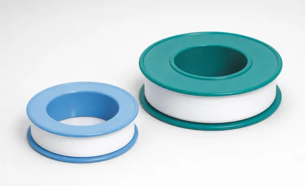
JST PTFE Pipe Thread Seal Tapes | Prevents Air & Moisture Infiltration | Fast Supply
JST PTFE Pipe Thread Seal Tapes for reliable sealing of pipe joints. Prevents air and moisture infiltration for stable system insulation and durabilit
View Details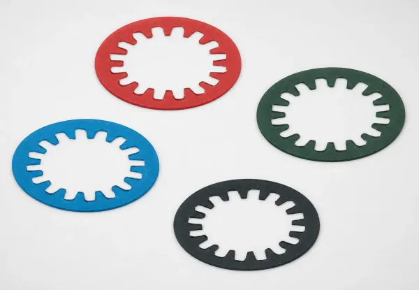
JMR Type Color Marker Rings for Water Flow Checkers | Reliable Identification | Durable Build
JMR Type Color Marker Rings for Water Flow Checkers help organize and identify cables or components during maintenance. Durable rings for reliable mar
View Details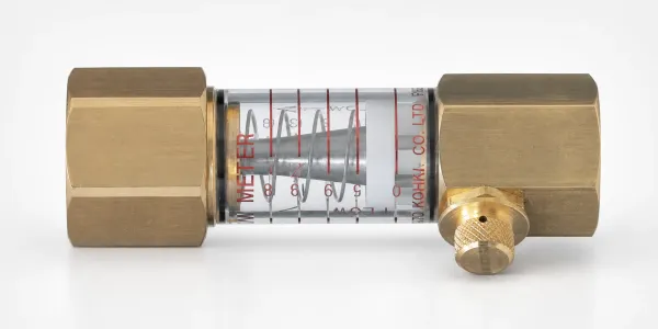
FLM-F Simple Flow Checkers for Cooling Water | Reliable Flow Monitoring
FLM-F Simple Flow Checkers for Cooling Water provide reliable flow-rate monitoring for stable cooling circulation, helping prevent overheating. Get de
View Details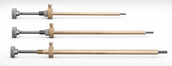
Cooling Circuit Plug Installation Tool for Sealing Cooling Channels | Fast Integration
Cooling circuit plug installation tool for sealing cooling channels, helping prevent leaks and protect coolant levels. Simple setup for reliable syste
View Details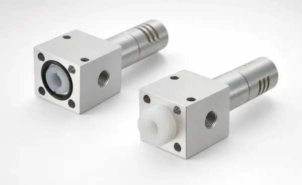
Compact Air Jet Coolers for Molds | Efficient Mold Temperature Control
Compact Air Jet Coolers for Molds deliver reliable high-speed jet cooling for stable injection molding temperature control. Reduce cycle time—request
View Details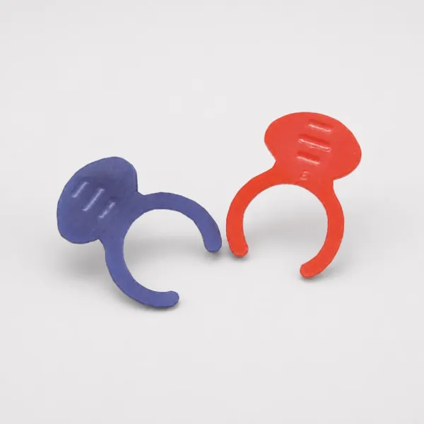
Safety Clips for Waterline Socket Connectors | Color Coded Hot/Cold | PCS
Safety Clips for waterline socket connectors help prevent accidental release of hose fittings. Color coded for hot and cold lines. Contact PCS.
View DetailsPipe vs Core/Cover — Selection Guide
| Factor | Outer/Inner Pipes | Inside Core/Outside Cover |
|---|---|---|
| Cooling Efficiency | Moderate | High (directed flow) |
| Best For | Wide flat sections, general cooling | Hot spots, gates, thick sections |
| Installation | Drops into drilled bore | Requires machined pocket |
| Flow Control | Limited (natural convection pattern) | Directed (forced circulation) |
| Cost | $ | $$ |
| Maintenance | Easy — pull and replace | Moderate — core/cover assembly |
Decision rule: Use Outer/Inner Pipes for compact cores (Ø10–30 mm) where space is limited. Use Inside Core/Outside Cover for larger cores (>Ø30 mm) where higher flow rates are needed for adequate heat removal. For detailed guidance, see our Pipe vs Core/Cover Cooling Units for Die Casting — How to Choose.
Why Die Casting Requires Dedicated Cooling
Die casting molds must remove 3–5× more heat per cycle than injection molds. Molten aluminum at 660°C releases ~390 kJ/kg of latent heat during solidification — nearly double the ~200 kJ/kg typical of thermoplastics. Standard drilled cooling channels cannot extract heat fast enough from thick sections or areas near gates, leading to hot spots that cause:
- Extended cycle times (10–30% longer)
- Porosity from incomplete solidification
- Accelerated die erosion at overheated zones
- Dimensional instability from thermal distortion
Dedicated cooling units provide targeted, high-flow-rate heat extraction exactly where it's needed.
Decision rule: Die casting cooling removes 3–5× more heat per cycle than injection molding due to molten metal temperatures (650°C vs 250°C). Standard drilled channels cannot achieve the required flow rates. For detailed guidance, see our How to Calculate Required Cooling Capacity for Die Casting Molds.
Application Scenarios
Gate Area Cooling
Metal enters at 30–60 m/s, creating extreme localized heating. Core/cover units positioned near gates extract heat before it damages the die surface.
Thick Section Cooling
Wall sections > 8 mm solidify last, creating shrinkage porosity. Pipe-type units embedded in the die block accelerate solidification from inside out.
Thin-wall die castings (<2 mm) solidify in <1 second, requiring aggressive cooling to prevent hot spots and shrinkage porosity. Core/Cover cooling units provide 3-5× the heat extraction rate of conventional drilled cooling channels.
Recommended: Inside Core/Outside Cover unit for cores >Ø30 mm
Decision rule: Position cooling units at hot spots identified by mold flow analysis — typically thick wall sections, gate areas, and core pins with L/D > 4. Coolant flow rate should achieve ΔT ≤ 4°C at the required heat extraction rate. For detailed guidance, see our How to Calculate Required Cooling Capacity for Die Casting Molds.
Frequently Asked Questions
Outer/Inner Pipes vs Inside Core/Outside Cover — which cooling unit design should I use?+
What coolant temperature and pressure are required for die casting cooling units?+
How do I calculate the required cooling capacity for a die casting mold?+
Engineering Resources
Need Cooling Units?
Send your mold layout showing hot spots. We will recommend the right cooling unit type and quantity.