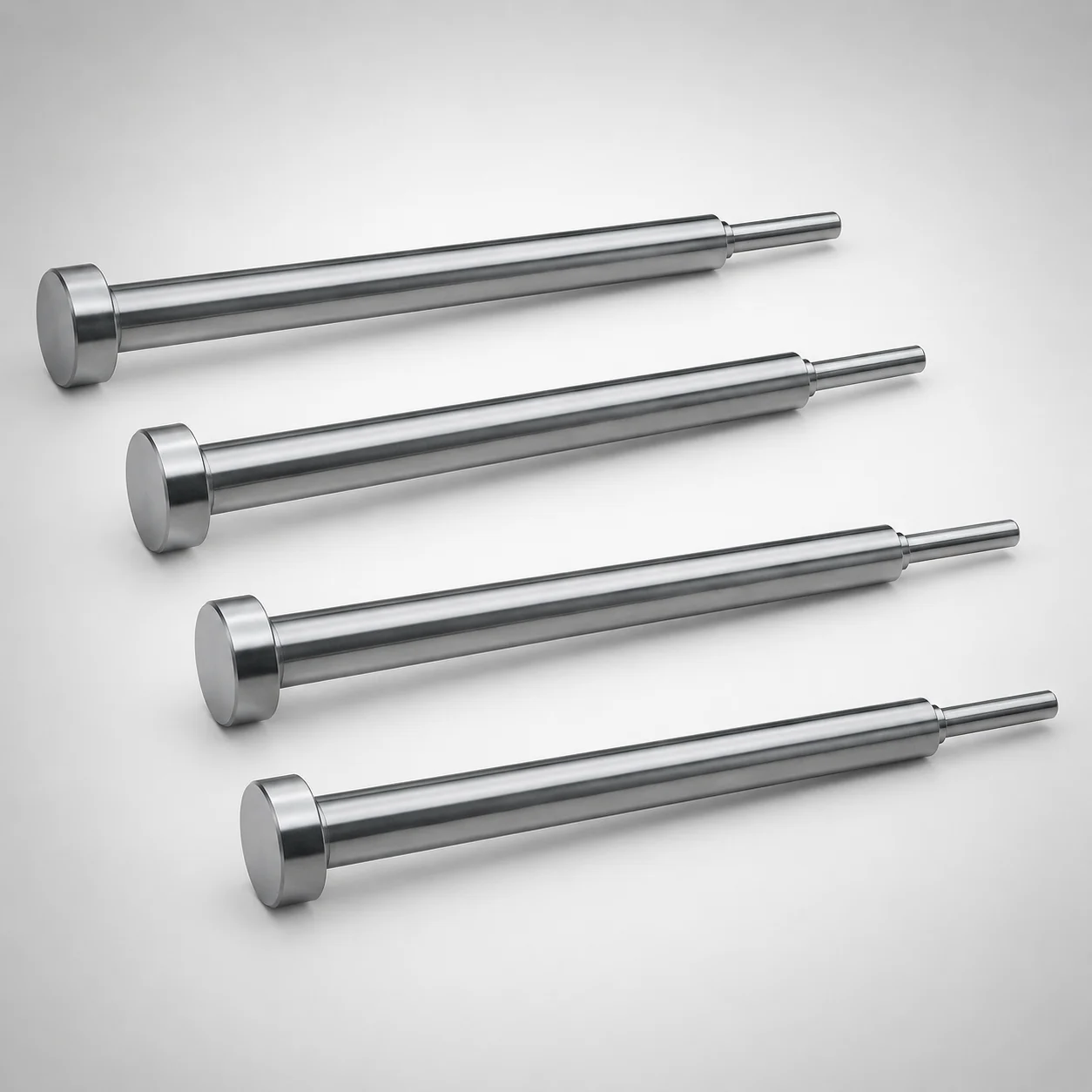
SKD61 Steel Taperless One-Step Center Pins
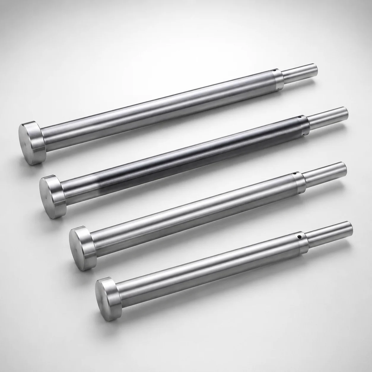
Taperless one-step center pins (SKD61 steel) with a nitrided surface treatment provide stable workpiece positioning for repeatable assembly and machining setups. Their one-step, taperless geometry supports consistent alignment without extra settling.
- One-step, taperless locating design for consistent positioning during mold/tool alignment
- Nitrided SKD61 steel construction enhances wear resistance for long service intervals
- Ground shaft diameter with fixed tolerance -0.01/-0.02 for reliable fit to sleeves
- Configurable length options help match different tooling stacks and application requirements
Specifications
661 configurations available
| Head Thickness | Shaft Diameter Tolerance | D/P (Shaft Diameter) (mm) | Step Shape | Tip Shape | A (Tip part) (mm) | C (Tip part) (mm) | F (Shaft diameter length) (mm) | G (Tip C chamfering width on the tip part) (mm) | K (Tip part angle) (°) | L (L dimension) (mm) | Q (Tip R chamfering on the tip part) (mm) | R (Tip part) (mm) | S (Tip tapered width on the tip part) (mm) | type |
|---|---|---|---|---|---|---|---|---|---|---|---|---|---|---|
| 6mm(JIS) | -0.01/-0.02 | 4 | B | No processing | 1 ~ 3.99 | - | 50 ~ 499.3 | - | - | 70 ~ 500 | - | - | - | - |
| 6mm(JIS) | -0.01/-0.02 | 4.5 | B | No processing | 1.5 ~ 4.49 | - | 50 ~ 499.3 | - | - | 70 ~ 500 | - | - | - | - |
| 6mm(JIS) | -0.01/-0.02 | 5 | B | No processing | 1.5 ~ 4.99 | - | 50 ~ 499.5 | - | - | 70 ~ 500 | - | - | - | - |
| 6mm(JIS) | -0.01/-0.02 | 5.5 | B | No processing | 2 ~ 5.49 | - | 50 ~ 499.5 | - | - | 70 ~ 500 | - | - | - | - |
| 6mm(JIS) | -0.01/-0.02 | 6 | B | No processing | 2 ~ 5.99 | - | 50 ~ 499.5 | - | - | 70 ~ 500 | - | - | - | - |
| 6mm(JIS) | -0.01/-0.02 | 6.5 | B | No processing | 2 ~ 6.49 | - | 50 ~ 499.5 | - | - | 70 ~ 500 | - | - | - | - |
| 6mm(JIS) | -0.01/-0.02 | 7 | B | No processing | 2 ~ 6.99 | - | 50 ~ 499.5 | - | - | 70 ~ 500 | - | - | - | - |
| 8mm(JIS) | -0.01/-0.02 | 8 | B | No processing | 2 ~ 7.99 | - | 50 ~ 499.5 | - | - | 70 ~ 500 | - | - | - | - |
| 8mm(JIS) | -0.01/-0.02 | 9 | B | No processing | 2 ~ 8.99 | - | 50 ~ 499.5 | - | - | 70 ~ 500 | - | - | - | - |
| 8mm(JIS) | -0.01/-0.02 | 10 | B | No processing | 2 ~ 9.99 | - | 50 ~ 499.5 | - | - | 70 ~ 500 | - | - | - | - |
| 8mm(JIS) | -0.01/-0.02 | 12 | B | No processing | 2 ~ 11.99 | - | 50 ~ 499.5 | - | - | 70 ~ 500 | - | - | - | - |
| 8mm(JIS) | - | 16 | B | No processing | 2.5 ~ 15.99 | - | 50 ~ 699.5 | - | - | 70 ~ 700 | - | - | - | - |
| 6mm(JIS) | -0.01/-0.02 | 4 | B | B | 1 ~ 3.99 | - | 50 ~ 499.3 | - | - | 70 ~ 500 | - | - | - | - |
| 6mm(JIS) | -0.01/-0.02 | 4.5 | B | B | 1.5 ~ 4.49 | - | 50 ~ 499.3 | - | - | 70 ~ 500 | - | - | - | - |
| 6mm(JIS) | -0.01/-0.02 | 5 | B | B | 1.5 ~ 4.99 | - | 50 ~ 499.5 | - | - | 70 ~ 500 | - | - | - | - |
| 6mm(JIS) | -0.01/-0.02 | 5.5 | B | B | 1.5 ~ 5.49 | - | 50 ~ 499.5 | - | - | 70 ~ 500 | - | - | - | - |
| 6mm(JIS) | -0.01/-0.02 | 6 | B | B | 2 ~ 5.99 | - | 50 ~ 499.5 | - | - | 70 ~ 500 | - | - | - | - |
| 6mm(JIS) | -0.01/-0.02 | 6.5 | B | B | 2 ~ 6.49 | - | 50 ~ 499.5 | - | - | 70 ~ 500 | - | - | - | - |
| 6mm(JIS) | -0.01/-0.02 | 7 | B | B | 2 ~ 6.99 | - | 50 ~ 499.5 | - | - | 70 ~ 500 | - | - | - | - |
| 8mm(JIS) | -0.01/-0.02 | 8 | B | B | 2 ~ 7.99 | - | 50 ~ 499.5 | - | - | 70 ~ 500 | - | - | - | - |
| 8mm(JIS) | -0.01/-0.02 | 9 | B | B | 2 ~ 8.99 | - | 50 ~ 499.5 | - | - | 70 ~ 500 | - | - | - | - |
| 8mm(JIS) | -0.01/-0.02 | 10 | B | B | 2 ~ 9.99 | - | 50 ~ 499.5 | - | - | 70 ~ 500 | - | - | - | - |
| 8mm(JIS) | -0.01/-0.02 | 12 | B | B | 2 ~ 11.99 | - | 50 ~ 499.5 | - | - | 70 ~ 500 | - | - | - | - |
| 8mm(JIS) | - | 16 | B | B | 2.5 ~ 15.99 | - | 50 ~ 699.5 | - | - | 70 ~ 700 | - | - | - | - |
| 6mm(JIS) | -0.01/-0.02 | 4 | B | C | 1 ~ 3.99 | - | 50 ~ 499.3 | 0.1 ~ 1.9 | - | 70 ~ 500 | - | - | - | - |
| 6mm(JIS) | -0.01/-0.02 | 4.5 | B | C | 1.5 ~ 4.49 | - | 50 ~ 499.3 | 0.5 ~ 2.2 | - | 70 ~ 500 | - | - | - | - |
| 6mm(JIS) | -0.01/-0.02 | 5 | B | C | 1.5 ~ 4.99 | - | 50 ~ 499.5 | 0.5 ~ 2.4 | - | 70 ~ 500 | - | - | - | - |
| 6mm(JIS) | -0.01/-0.02 | 5.5 | B | C | 1.5 ~ 5.49 | - | 50 ~ 499.5 | 0.5 ~ 2.7 | - | 70 ~ 500 | - | - | - | - |
| 6mm(JIS) | -0.01/-0.02 | 6 | B | C | 2 ~ 5.99 | - | 50 ~ 499.5 | 0.5 ~ 2.9 | - | 70 ~ 500 | - | - | - | - |
| 6mm(JIS) | -0.01/-0.02 | 6.5 | B | C | 2 ~ 6.49 | - | 50 ~ 499.5 | 0.5 ~ 3.2 | - | 70 ~ 500 | - | - | - | - |
| 6mm(JIS) | -0.01/-0.02 | 7 | B | C | 2 ~ 6.99 | - | 50 ~ 499.5 | 0.5 ~ 3.4 | - | 70 ~ 500 | - | - | - | - |
| 8mm(JIS) | -0.01/-0.02 | 8 | B | C | 2 ~ 7.99 | - | 50 ~ 499.5 | 0.5 ~ 3.9 | - | 70 ~ 500 | - | - | - | - |
| 8mm(JIS) | -0.01/-0.02 | 9 | B | C | 2 ~ 8.99 | - | 50 ~ 499.5 | 0.5 ~ 3.9 | - | 70 ~ 500 | - | - | - | - |
| 8mm(JIS) | -0.01/-0.02 | 10 | B | C | 2 ~ 9.99 | - | 50 ~ 499.5 | 0.5 ~ 4.9 | - | 70 ~ 500 | - | - | - | - |
| 8mm(JIS) | -0.01/-0.02 | 12 | B | C | 2 ~ 11.99 | - | 50 ~ 499.5 | 0.5 ~ 6.4 | - | 70 ~ 500 | - | - | - | - |
| 8mm(JIS) | - | 16 | B | C | 2.5 ~ 15.99 | - | 50 ~ 699.5 | 0.5 ~ 6.4 | - | 70 ~ 700 | - | - | - | - |
| 6mm(JIS) | -0.01/-0.02 | 4.5 | B | G | 1.5 ~ 4.49 | - | 50 ~ 499.3 | - | 21 ~ 60 | 70 ~ 500 | - | - | - | - |
| 6mm(JIS) | -0.01/-0.02 | 5 | B | G | 1.5 ~ 4.99 | - | 50 ~ 499.5 | - | 21 ~ 60 | 70 ~ 500 | - | - | - | - |
| 6mm(JIS) | -0.01/-0.02 | 5.5 | B | G | 1.5 ~ 5.49 | - | 50 ~ 499.5 | - | 21 ~ 60 | 70 ~ 500 | - | - | - | - |
| 6mm(JIS) | -0.01/-0.02 | 6 | B | G | 2 ~ 5.99 | - | 50 ~ 499.5 | - | 21 ~ 60 | 70 ~ 500 | - | - | - | - |
| 6mm(JIS) | -0.01/-0.02 | 6.5 | B | G | 2 ~ 6.49 | - | 50 ~ 499.5 | - | 21 ~ 60 | 70 ~ 500 | - | - | - | - |
| 6mm(JIS) | -0.01/-0.02 | 7 | B | G | 2 ~ 6.99 | - | 50 ~ 499.5 | - | 21 ~ 60 | 70 ~ 500 | - | - | - | - |
| 8mm(JIS) | -0.01/-0.02 | 8 | B | G | 2 ~ 7.99 | - | 50 ~ 499.5 | - | 21 ~ 60 | 70 ~ 500 | - | - | - | - |
| 8mm(JIS) | -0.01/-0.02 | 9 | B | G | 2 ~ 8.99 | - | 50 ~ 499.5 | - | 21 ~ 60 | 70 ~ 500 | - | - | - | - |
| 8mm(JIS) | -0.01/-0.02 | 10 | B | G | 2 ~ 9.99 | - | 50 ~ 499.5 | - | 21 ~ 60 | 70 ~ 500 | - | - | - | - |
| 8mm(JIS) | -0.01/-0.02 | 12 | B | G | 2 ~ 11.99 | - | 50 ~ 499.5 | - | 21 ~ 60 | 70 ~ 500 | - | - | - | - |
| 6mm(JIS) | -0.01/-0.02 | 4.5 | B | R | 1.5 ~ 4.49 | - | 50 ~ 499.3 | - | - | 70 ~ 500 | 0.2 ~ 2.2 | - | - | - |
| 6mm(JIS) | -0.01/-0.02 | 5.5 | B | R | 1.5 ~ 5.49 | - | 50 ~ 499.5 | - | - | 70 ~ 500 | 0.2 ~ 2.7 | - | - | - |
| 6mm(JIS) | -0.01/-0.02 | 6 | B | R | 2 ~ 5.99 | - | 50 ~ 499.5 | - | - | 70 ~ 500 | 0.2 ~ 2.9 | - | - | - |
| 6mm(JIS) | -0.01/-0.02 | 6.5 | B | R | 2 ~ 6.49 | - | 50 ~ 499.5 | - | - | 70 ~ 500 | 0.2 ~ 3.2 | - | - | - |
Product Guide
Application Scenarios+
Taperless one-step center pins are used in injection mold tooling wherever stable, repeatable part registration is required—especially in multi-up assemblies and precision machining setups. Their taperless, one-step geometry supports consistent alignment during mold/tool positioning, reducing settling that can shift workpiece location.
- Automotive connector and bracket molds: Use these pins to maintain register between cavity inserts and ejector-side tooling, supporting repeatable assembly when high cycle rates demand long-term positional stability.
- Medical device housing molds: The nitrided SKD61 surface improves wear resistance at the locating interface, helping preserve alignment through repeated clamp-open cycles where dimensional control is critical.
- Electronics enclosure tooling: Configurable lengths (L ranges up to 700 mm depending on variant) help match different stack heights, enabling correct engagement with mating sleeves without excessive interference.
The ground shaft diameter with the specified tolerance is well-suited for precision locating fits to sleeves, supporting reliable repeatability across production runs.
Material & Process Details+
The pins are manufactured from SKD61 steel, a hot-work tool steel commonly aligned with H13 (AISI equivalent) in performance class. SKD61 provides a practical balance of toughness and hot/dynamic wear resistance for tooling components subjected to repeated loading.
- Nitrided surface treatment: A nitrided layer increases surface hardness and wear resistance at the locating contact area, helping maintain dimensional stability over time.
- Hardness & trade-offs: Nitriding improves wear resistance, but the core toughness still governs impact and bending resilience; adequate strength is required to avoid deformation in tight alignment stacks.
- Manufacturing approach: Ground shaft finishing supports the specified fit tolerance for sleeve engagement, while the one-step taperless form minimizes geometric variability during tool alignment.
If compared to non-nitrided variants, the nitrided surface typically offers improved wear life at the locating interface, at the expense of additional surface-processing steps.
Sizing & Selection Guide+
Select the center pin dimensions by matching the shaft diameter and locating features to the mating sleeve/core registration requirements. The shaft diameter D/P is available in 1.5 ~ 16 mm, and the design-fit is controlled by a fixed shaft diameter tolerance of -0.01/-0.02—use this when you define clearance/press-fit with the sleeve.
- Choose D/P first: Pick the shaft diameter within 1.5 ~ 16 mm that matches the sleeve bore specification; account for the negative tolerance to avoid overly tight engagement.
- Verify engagement length: The length dimension L is offered in multiple ranges depending on configuration (e.g., 70 ~ 500, 70 ~ 700, 70 ~ 200, 70 ~ 400).
- Select head thickness: Head thickness options are 6 mm (JIS), 8 mm (JIS), or 4 mm (T4), which should align with your stack-up to control seating height.
The step shape (B/C/D/E) and tip shape (e.g., No processing, B, C, G, R, T) affect how the pin interfaces with the mating part; select the variant that matches the required step geometry and tip engagement depth.
Frequently Asked Questions
How should I match the pin shaft diameter (D/P) to the locating sleeve bore for a stable taperless one-step fit?+
Select D/P (shaft diameter) within 1.5 ~ 16 mm and use the fixed shaft diameter tolerance -0.01/-0.02 when defining sleeve clearance. Because the tolerance is negative, the as-made shaft can be smaller than nominal, which may affect press-fit assumptions. Validate the engagement condition against your sleeve bore tolerance and desired locating stiffness.
What tip and step variants are available, and how do they affect alignment interface design?+
Step shapes are available as B, C, D, E. Tip shapes include options such as No processing, B, C, G, R, T, and related tip geometry parameters (for example, A = 0.5 ~ 2.5 mm, and tip angle K = 21 ~ 60° with variant-specific ranges). These features change the contact and engagement characteristics with the mating part, so match them to your sleeve/core registration strategy rather than relying only on shaft diameter.
Does the nitrided SKD61 surface meaningfully improve locating pin wear in production?+
Yes. The pins use SKD61 steel with a nitrided surface, which is intended to enhance wear resistance at the locating interface. This helps maintain positional repeatability across repeated clamp-open cycles. For tools that experience frequent alignment contact, the nitriding step supports longer service intervals compared to untreated surfaces.
How do I choose the correct length (L) and head thickness for my mold/tool stack-up?+
Choose L from the available ranges (e.g., 70 ~ 500, 70 ~ 700, 70 ~ 200, 70 ~ 400 mm) based on your required engagement length. Then select head thickness as 6 mm (JIS), 8 mm (JIS), or 4 mm (T4) to match seating height. Confirm that the pin engages the sleeve/core without bottoming out or leaving insufficient contact length.
Which hardness and toughness considerations should I account for with nitrided SKD61 pins?+
Nitriding is designed to increase surface hardness and wear resistance at the contact area, while the SKD61 core toughness governs resistance to bending and impact in alignment stacks. When specifying for durability, consider that improving surface wear does not automatically guarantee resistance to misalignment-induced loads. Ensure your design maintains stable clamp force and alignment to prevent excessive shear or deflection at the one-step interface.
Related Products
Need Custom Specifications?
Our engineering team can help with custom configurations, material selection, and volume pricing.