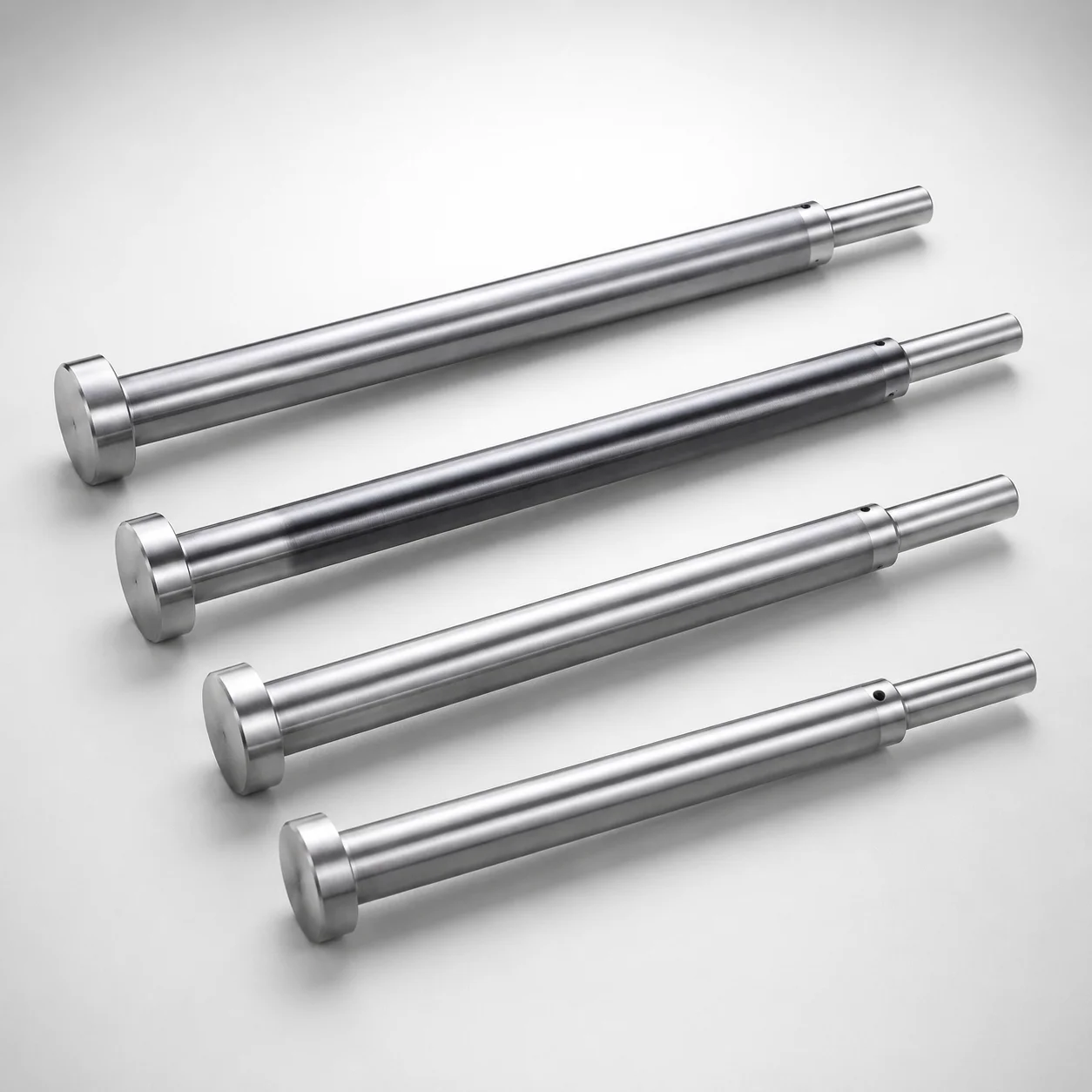
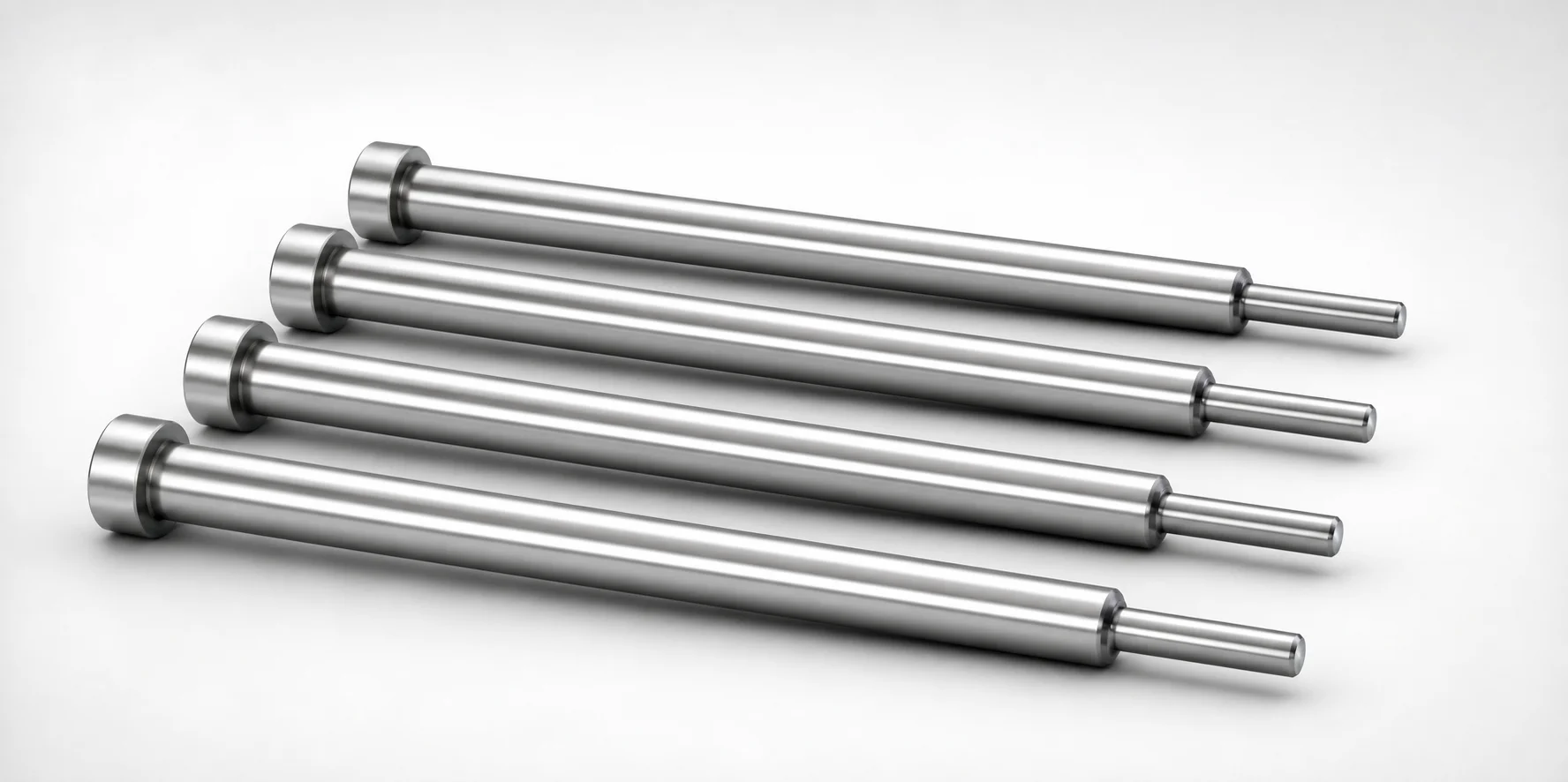
DIN Standard SKD61 Steel Nitrided Taperless One-Step Center Pins with Cooling Hole
Taperless one-step center pins with cooling hole (SKD61 steel) provide reliable one-piece alignment for molds while maintaining controlled temperature with a built-in cooling hole option. Nitrided surface treatment enhances wear resistance during repeated cycles.
- One-step, taperless geometry supports stable centering without a taper during press alignment
- Nitrided SKD61 steel construction improves scuff resistance and long service life
- Precision fit for sleeve interfaces using reference shaft diameter tolerance and H7 compatible sleeve-hole reference
- DIN-compatible form factor suitable for tooling that requires tight mold positioning and optional cooling
Specifications
264 configurations available
| Head Thickness | D/P (Shaft Diameter) (mm) | Step Shape | Tip Shape | A (Tip part) (mm) | C (Tip part) (mm) | F (Shaft diameter length) (mm) | G (Tip C chamfering width on the tip part) (mm) | K (Tip part angle) (°) | L (L dimension) (mm) | Q (Tip R chamfering on the tip part) (mm) | R (Tip part) (mm) | S (Tip tapered width on the tip part) (mm) | W (Cooling hole diameter) (mm) | type |
|---|---|---|---|---|---|---|---|---|---|---|---|---|---|---|
| 6mm(JIS) | 6 | B | No processing | 5 ~ 5.97 | - | 70 ~ 149.5 | - | - | 70 ~ 150 | - | - | - | 3 | - |
| 6mm(JIS) | 7 | B | No processing | 6 ~ 6.97 | - | 70 ~ 149.5 | - | - | 70 ~ 150 | - | - | - | 3 | - |
| 8mm(JIS) | 8 | B | No processing | 7 ~ 7.97 | - | 70 ~ 199.5 | - | - | 70 ~ 200 | - | - | - | 4 | - |
| 8mm(JIS) | 10 | B | No processing | 8 ~ 9.97 | - | 70 ~ 249.5 | - | - | 70 ~ 250 | - | - | - | 5 ~ 6.5 | - |
| 8mm(JIS) | 12 | B | No processing | 9 ~ 11.97 | - | 70 ~ 249.5 | - | - | 70 ~ 250 | - | - | - | 6 ~ 8.5 | - |
| 8mm(JIS) | 16 | B | No processing | 9 ~ 15.97 | - | 70 ~ 249.5 | - | - | 70 ~ 250 | - | - | - | 6 ~ 12.5 | - |
| 6mm(JIS) | 6 | B | B | 5 ~ 5.97 | - | 70 ~ 149.5 | - | - | 70 ~ 150 | - | - | - | 3 | - |
| 6mm(JIS) | 7 | B | B | 6 ~ 6.97 | - | 70 ~ 149.5 | - | - | 70 ~ 150 | - | - | - | 3 | - |
| 8mm(JIS) | 8 | B | B | 7 ~ 7.97 | - | 70 ~ 199.5 | - | - | 70 ~ 200 | - | - | - | 4 | - |
| 8mm(JIS) | 10 | B | B | 8 ~ 9.97 | - | 70 ~ 249.5 | - | - | 70 ~ 250 | - | - | - | 5 ~ 6.5 | - |
| 8mm(JIS) | 12 | B | B | 9 ~ 11.97 | - | 70 ~ 249.5 | - | - | 70 ~ 250 | - | - | - | 6 ~ 8.5 | - |
| 8mm(JIS) | 16 | B | B | 9 ~ 15.97 | - | 70 ~ 249.5 | - | - | 70 ~ 250 | - | - | - | 6 ~ 12.5 | - |
| 6mm(JIS) | 6 | B | C | 5 ~ 5.97 | - | 70 ~ 149.5 | 0.5 ~ 2.9 | - | 70 ~ 150 | - | - | - | 3 | - |
| 6mm(JIS) | 7 | B | C | 6 ~ 6.97 | - | 70 ~ 149.5 | 0.5 ~ 3.4 | - | 70 ~ 150 | - | - | - | 3 | - |
| 8mm(JIS) | 8 | B | C | 7 ~ 7.97 | - | 70 ~ 199.5 | 0.5 ~ 3.9 | - | 70 ~ 200 | - | - | - | 4 | - |
| 8mm(JIS) | 10 | B | C | 8 ~ 9.97 | - | 70 ~ 249.5 | 0.5 ~ 4.9 | - | 70 ~ 250 | - | - | - | 5 ~ 6.5 | - |
| 8mm(JIS) | 12 | B | C | 9 ~ 11.97 | - | 70 ~ 249.5 | 0.5 ~ 5.9 | - | 70 ~ 250 | - | - | - | 6 ~ 8.5 | - |
| 8mm(JIS) | 16 | B | C | 9 ~ 15.97 | - | 70 ~ 249.5 | 0.5 ~ 7.9 | - | 70 ~ 250 | - | - | - | 6 ~ 12.5 | - |
| 6mm(JIS) | 6 | B | G | 5 ~ 5.97 | - | 70 ~ 149.5 | - | 1 ~ 60 | 70 ~ 150 | - | - | - | 3 | - |
| 6mm(JIS) | 7 | B | G | 6 ~ 697 | - | 70 ~ 149.5 | - | 1 ~ 60 | 70 ~ 150 | - | - | - | 3 | - |
| 8mm(JIS) | 8 | B | G | 7 ~ 7.97 | - | 70 ~ 199.5 | - | 1 ~ 60 | 70 ~ 200 | - | - | - | 4 | - |
| 8mm(JIS) | 10 | B | G | 8 ~ 9.97 | - | 70 ~ 249.5 | - | 1 ~ 60 | 70 ~ 250 | - | - | - | 5 ~ 6.5 | - |
| 8mm(JIS) | 12 | B | G | 9 ~ 11.97 | - | 70 ~ 249.5 | - | 1 ~ 60 | 70 ~ 250 | - | - | - | 6 ~ 8.5 | - |
| 8mm(JIS) | 16 | B | G | 9 ~ 15.97 | - | 70 ~ 249.5 | - | 1 ~ 60 | 70 ~ 250 | - | - | - | 6 ~ 12.5 | - |
| 6mm(JIS) | 6 | B | R | 5 ~ 5.97 | - | 70 ~ 149.5 | - | - | 70 ~ 150 | 0.2 ~ 2.9 | - | - | 3 | - |
| 6mm(JIS) | 7 | B | R | 6 ~ 6.97 | - | 70 ~ 149.5 | - | - | 70 ~ 150 | 0.2 ~ 3.4 | - | - | 3 | - |
| 8mm(JIS) | 8 | B | R | 7 ~ 7.97 | - | 70 ~ 199.5 | - | - | 70 ~ 200 | 0.2 ~ 3.9 | - | - | 4 | - |
| 8mm(JIS) | 10 | B | R | 8 ~ 9.97 | - | 70 ~ 249.5 | - | - | 70 ~ 250 | 0.2 ~ 4.9 | - | - | 5 ~ 6.5 | - |
| 8mm(JIS) | 12 | B | R | 9 ~ 11.97 | - | 70 ~ 249.5 | - | - | 70 ~ 250 | 0.2 ~ 5.9 | - | - | 6 ~ 8.5 | - |
| 8mm(JIS) | 16 | B | R | 9 ~ 15.97 | - | 70 ~ 249.5 | - | - | 70 ~ 250 | 0.2 ~ 7.9 | - | - | 6 ~ 12.5 | - |
| 6mm(JIS) | 6 | B | T | 5 ~ 5.97 | - | 70 ~ 149.5 | - | 1 ~ 45 | 70 ~ 150 | - | - | 0.1 ~ 50 | 3 | - |
| 6mm(JIS) | 7 | B | T | 6 ~ 6.97 | - | 50 ~ 149.5 | - | 1 ~ 45 | 70 ~ 150 | - | - | 0.1 ~ 50 | 3 | - |
| 8mm(JIS) | 8 | B | T | 7 ~ 7.97 | - | 70 ~ 199.5 | - | 1 ~ 45 | 70 ~ 200 | - | - | 0.1 ~ 50 | 4 | - |
| 8mm(JIS) | 10 | B | T | 8 ~ 9.97 | - | 70 ~ 249.5 | - | 1 ~ 45 | 70 ~ 250 | - | - | 0.1 ~ 50 | 5 ~ 6.5 | - |
| 8mm(JIS) | 12 | B | T | 9 ~ 11.97 | - | 70 ~ 249.5 | - | 1 ~ 45 | 70 ~ 250 | - | - | 0.1 ~ 50 | 6 ~ 8.5 | - |
| 8mm(JIS) | 16 | B | T | 9 ~ 15.97 | - | 70 ~ 249.5 | - | 1 ~ 45 | 70 ~ 250 | - | - | 0.1 ~ 50 | 6 ~ 12.5 | - |
| 6mm(JIS) | 6 | C | No processing | 5 ~ 5.99 | - | 70 ~ 149.5 | - | - | 70 ~ 150 | - | - | - | 3 | - |
| 6mm(JIS) | 7 | C | No processing | 6 ~ 6.99 | - | 70 ~ 149.5 | - | - | 70 ~ 150 | - | - | - | 3 | - |
| 8mm(JIS) | 8 | C | No processing | 7 ~ 7.99 | - | 70 ~ 199.5 | - | - | 70 ~ 200 | - | - | - | 4 | - |
| 8mm(JIS) | 10 | C | No processing | 8 ~ 9.99 | - | 70 ~ 249.5 | - | - | 70 ~ 250 | - | - | - | 5 ~ 6.5 | - |
| 8mm(JIS) | 12 | C | No processing | 9 ~ 11.99 | - | 70 ~ 249.5 | - | - | 70 ~ 250 | - | - | - | 6 ~ 8.5 | - |
| 8mm(JIS) | 16 | C | No processing | 9 ~ 15.99 | - | 70 ~ 249.5 | - | - | 70 ~ 250 | - | - | - | 6 ~ 12.5 | - |
| 6mm(JIS) | 6 | C | B | 5 ~ 5.99 | - | 70 ~ 149.5 | - | - | 70 ~ 150 | - | - | - | 3 | - |
| 6mm(JIS) | 7 | C | B | 6 ~ 6.99 | - | 70 ~ 149.5 | - | - | 70 ~ 150 | - | - | - | 3 | - |
| 8mm(JIS) | 8 | C | B | 7 ~ 7.99 | - | 70 ~ 199.5 | - | - | 70 ~ 200 | - | - | - | 4 | - |
| 8mm(JIS) | 10 | C | B | 8 ~ 9.99 | - | 70 ~ 249.5 | - | - | 70 ~ 250 | - | - | - | 5 ~ 6.5 | - |
| 8mm(JIS) | 12 | C | B | 9 ~ 11.99 | - | 70 ~ 249.5 | - | - | 70 ~ 250 | - | - | - | 6 ~ 8.5 | - |
| 8mm(JIS) | 16 | C | B | 9 ~ 15.99 | - | 70 ~ 249.5 | - | - | 70 ~ 250 | - | - | - | 6 ~ 12.5 | - |
| 6mm(JIS) | 6 | C | C | 5 ~ 5.99 | - | 70 ~ 149.5 | 0.5 ~ 2.9 | - | 70 ~ 150 | - | - | - | 3 | - |
| 6mm(JIS) | 7 | C | C | 6 ~ 6.99 | - | 70 ~ 149.5 | 0.5 ~ 3.4 | - | 70 ~ 150 | - | - | - | 3 | - |
Product Guide
Application Scenarios+
Taperless one-step center pins are used in injection mold assemblies to establish repeatable alignment between the cavity side and core side during press closure. Because they are taperless and designed as a one-step locating element, they help maintain stable centering even when tooling is cycled at high frequency.
- Automotive connector and sensor housing molds: The nitrided SKD61 surface supports scuff and wear resistance at the alignment interface, while the integrated location geometry reduces positional drift over long runs.
- Medical device housings and thin-wall components: Consistent alignment improves cosmetic and dimensional quality around shut-off lines; the built-in cooling hole option supports more controlled local temperature near the locating region.
- Electronics packaging and precision inserts: Engineers can match the pin length range (e.g., up to L 70–250 mm) to achieve correct engagement depth with sleeve interfaces.
This variant is suited for applications that require tight positioning and optional thermal management without relying on a taper for alignment.
Material & Process Details+
This product uses DIN Standard SKD61 steel, a hot-work tool steel commonly treated as an H13/AISI equivalent for tooling applications. SKD61 provides a balance of wear resistance and toughness, making it suitable for locating components that experience repeated sliding/impact during mold closing.
- Surface treatment: The pins are nitrided, which increases surface hardness and wear/scuff resistance for the high-contact alignment area.
- Heat treatment state: Expected condition is quenched & tempered prior to nitriding, followed by a nitrided surface layer to improve durability.
Nitriding typically improves resistance to abrasion while slightly reducing core ductility compared with an untreated condition—so the underlying SKD61 toughness from its tempered state remains important for fatigue performance.
Sizing & Selection Guide+
Selection starts with the shaft diameter (D/P) because it must interface with the sleeve-hole reference. Choose among the available D/P values: 6, 7, 8, 10, 12, 16 mm to match your locating sleeve and center-hole system.
- Engagement length: Match the available F (shaft diameter length) and L (overall length) to ensure correct seating without bottoming. F is available across ranges including 70–149.5, 70–199.5, 70–249.5, and 50–149.5 mm, while L is available as 70–150, 70–200, and 70–250 mm.
- Head thickness: Confirm head thickness options of 4 mm (T4) or 6/8 mm (JIS) to fit your tooling plate stack-up.
- Cooling hole diameter: Select W from 3, 4, 5–6.5, 6–8.5, or 6–12.5 mm based on desired thermal performance.
Use design references that accommodate standard fit practices (e.g., the product notes H7-compatible sleeve-hole reference) and validate clearance to prevent binding at maximum thermal expansion.
Frequently Asked Questions
Which shaft diameter (D/P) should I select for compatibility with my center-sleeve holes?+
Select the D/P value from the available options (6, 7, 8, 10, 12, 16 mm) that matches your locating sleeve-hole reference. The product is intended for sleeve interfaces designed around an H7-compatible reference. Verify clearance at assembly temperature and confirm that your sleeve bore tolerance aligns with your mold-closing alignment requirements.
How do I choose the correct pin length (F and L) to avoid insufficient engagement or bottoming?+
Use F (shaft diameter length) to set the required engagement zone within the mold’s sleeve/head interface. The available F ranges include 70–149.5, 70–199.5, 70–249.5, and 50–149.5 mm, depending on configuration, and L is offered across 70–150, 70–200, and 70–250 mm. Match these to your cavity/core stack-up so the pin seats correctly without contacting hard stops under thermal expansion.
What does nitriding on SKD61 improve for one-step taperless center pins?+
Nitriding increases surface wear and scuff resistance at the high-contact alignment area. With SKD61 steel, this helps maintain stable centering and reduces degradation from repeated press cycles. The result is improved durability where sliding micro-movements can occur during mold closure.
When should I specify the cooling hole diameter (W) for center pin temperature control?+
If local temperature management near the alignment interface is required, choose the W cooling hole diameter from 3, 4, 5–6.5, 6–8.5, or 6–12.5 mm. Select the diameter based on cooling channel routing limits and the desired thermal response time. Ensure cooling lines and seals in the tooling design are compatible with the selected W geometry.
How do the step shape and tip shape options affect alignment performance?+
The product supports multiple step shapes (B, C, D, E) and tip shapes (No processing, B, C, G, R, T) to tailor locating behavior and edge geometry at the interface. Choose the option that matches your sleeve chamfers/leading profiles and shut-off requirements. If your design emphasizes lead-in accuracy, consider tip processing variants (B/C/G/R/T) that provide controlled front geometry.
Related Products
Need Custom Specifications?
Our engineering team can help with custom configurations, material selection, and volume pricing.