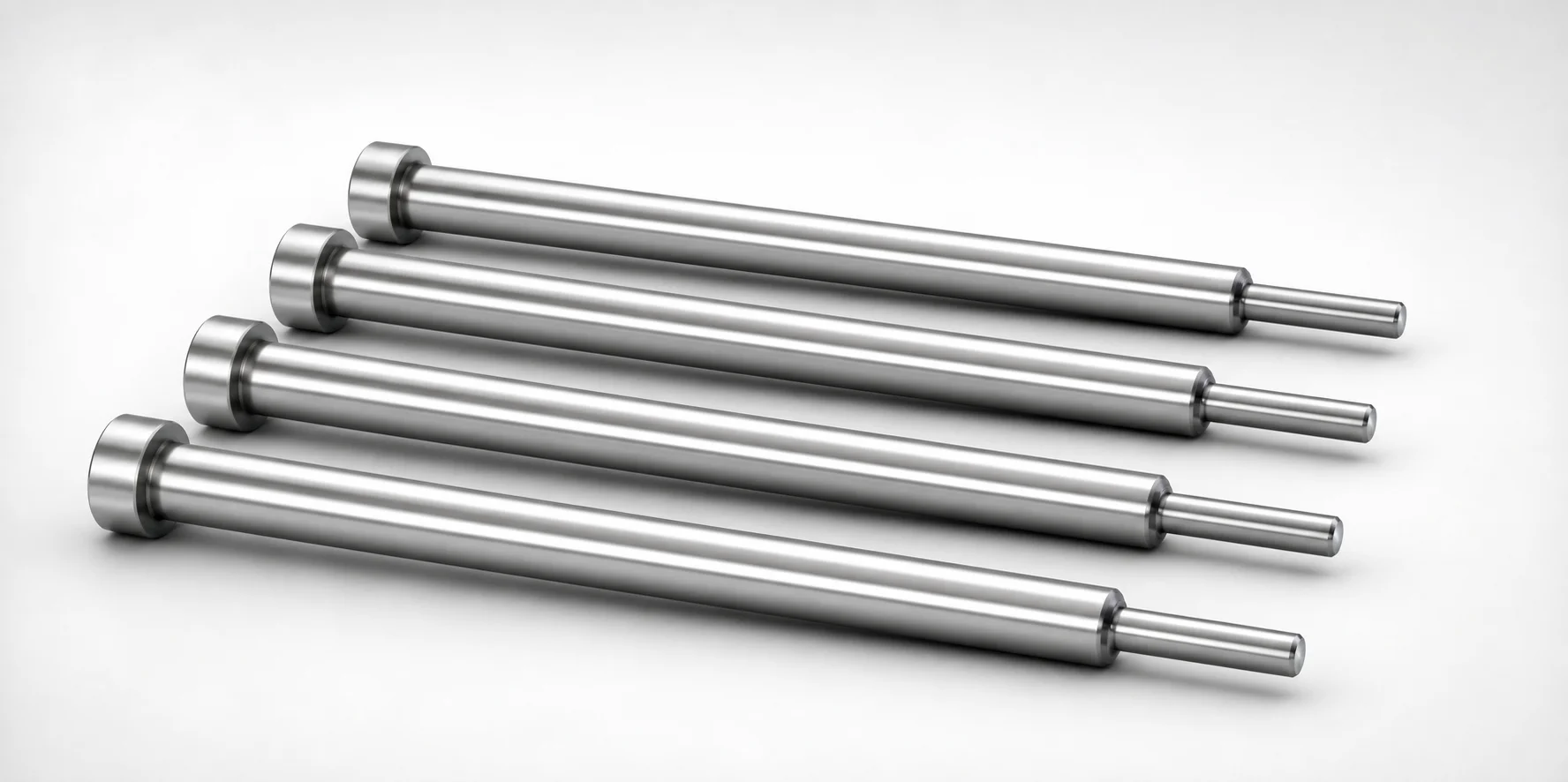
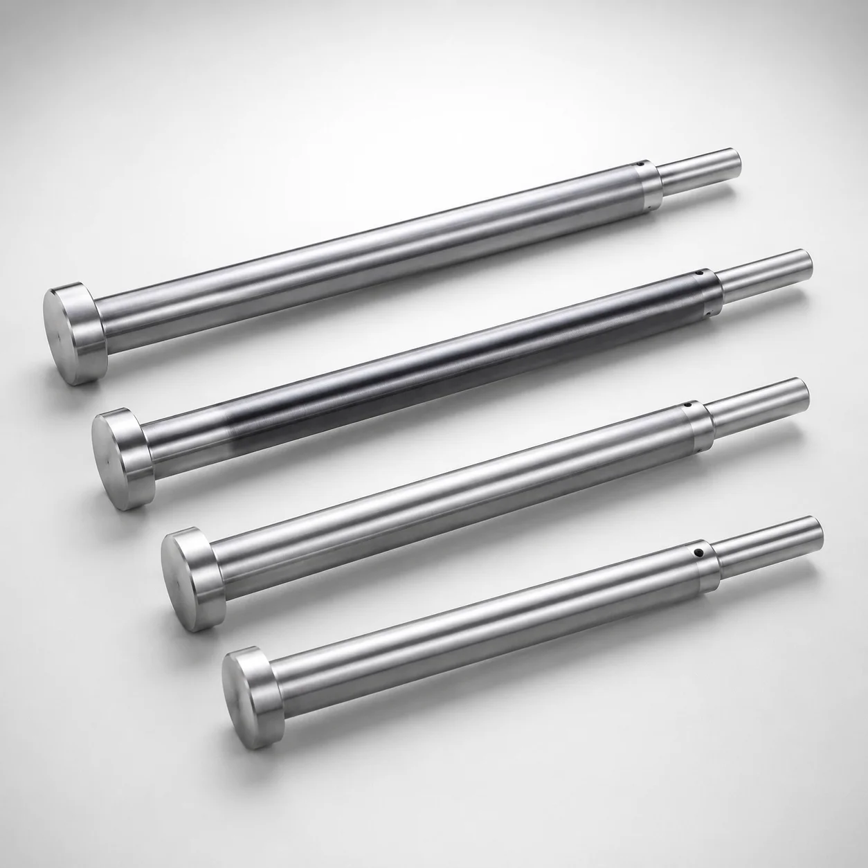
SKD61 Steel Taperless One-Step Center Pins with Nitrided Surface
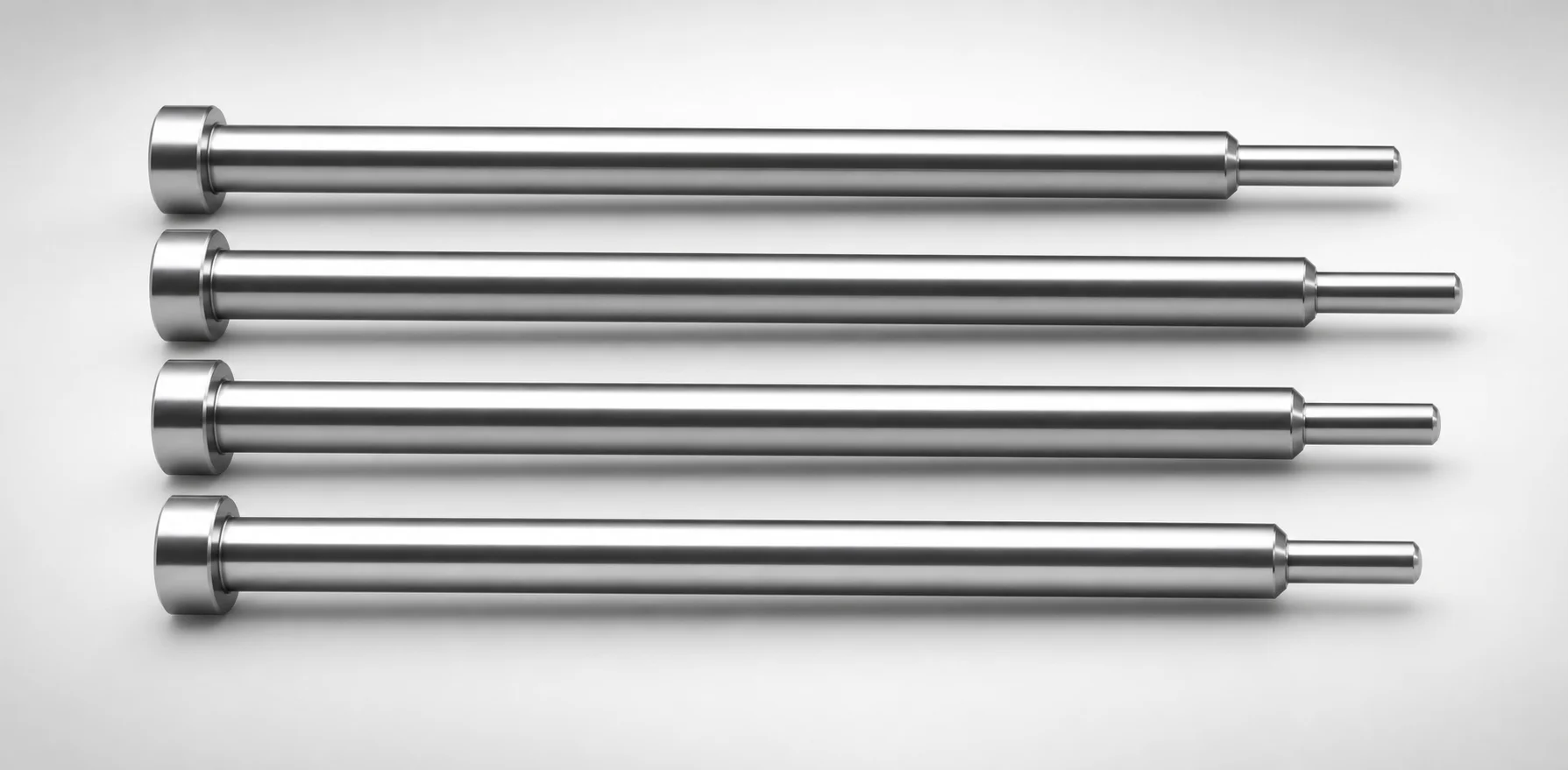
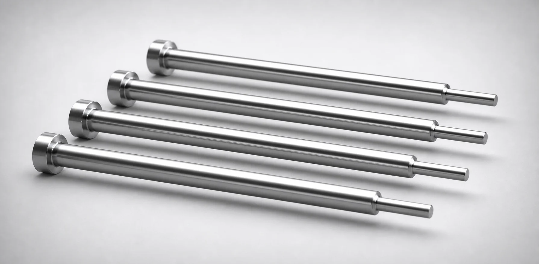
Taperless one-step center pins (SKD61 steel) with nitrided surface treatment deliver stable, step-free location for repeatable mold center alignment. The nitrided layer enhances wear resistance for longer service intervals.
- One-step, taperless pin geometry for consistent centering during setup and operation
- Nitrided SKD61 steel surface improves abrasion resistance in mold cycles
- Sleeve-hole interface support to maintain fit under controlled bore tolerances
- Suitable for precision mold component assemblies requiring reliable centering
Specifications
618 configurations available
| Head Thickness | Shaft Diameter Tolerance | D/P (Shaft Diameter) (mm) | Step Shape | Tip Shape | No. (Nominal diameter) (mm) | A (Tip part) (mm) | C (Tip part) (mm) | F (Shaft diameter length) (mm) | G (Tip C chamfering width on the tip part) (mm) | K (Tip part angle) (°) | L (L dimension) (mm) | Q (Tip R chamfering on the tip part) (mm) | R (Tip part) (mm) | S (Tip tapered width on the tip part) (mm) | type |
|---|---|---|---|---|---|---|---|---|---|---|---|---|---|---|---|
| 6mm(JIS) | -0.01/-0.02 | 3.5 ~ 3.99 | B | No processing | 4 | 1 ~ 3.99 | - | 50 ~ 499.5 | - | - | 70 ~ 500 | - | - | - | - |
| 6mm(JIS) | -0.01/-0.02 | 4 ~ 4.49 | B | No processing | 4.5 | 1.5 ~ 4.49 | - | 50 ~ 499.5 | - | - | 70 ~ 500 | - | - | - | - |
| 6mm(JIS) | -0.01/-0.02 | 4.5 ~ 4.99 | B | No processing | 5 | 1.5 ~ 4.99 | - | 50 ~ 499.5 | - | - | 70 ~ 500 | - | - | - | - |
| 6mm(JIS) | -0.01/-0.02 | 5 ~ 5.49 | B | No processing | 5.5 | 2 ~ 5.49 | - | 50 ~ 499.5 | - | - | 70 ~ 500 | - | - | - | - |
| 6mm(JIS) | -0.01/-0.02 | 5.5 ~ 5.99 | B | No processing | 6 | 2 ~ 5.99 | - | 50 ~ 599.5 | - | - | 70 ~ 600 | - | - | - | - |
| 6mm(JIS) | -0.01/-0.02 | 6 ~ 6.49 | B | No processing | 6.5 | 2 ~ 6.49 | - | 50 ~ 599.5 | - | - | 70 ~ 600 | - | - | - | - |
| 6mm(JIS) | -0.01/-0.02 | 6.5 ~ 6.99 | B | No processing | 7 | 2 ~ 6.99 | - | 50 ~ 599.5 | - | - | 70 ~ 600 | - | - | - | - |
| 8mm(JIS) | -0.01/-0.02 | 7 ~ 7.99 | B | No processing | 8 | 2 ~ 7.99 | - | 50 ~ 599.5 | - | - | 70 ~ 600 | - | - | - | - |
| 8mm(JIS) | -0.01/-0.02 | 8 ~ 9.99 | B | No processing | 10 | 2 ~ 9.99 | - | 50 ~ 599.5 | - | - | 70 ~ 600 | - | - | - | - |
| 8mm(JIS) | -0.01/-0.02 | 10 ~ 11.99 | B | No processing | 12 | 2 ~ 11.99 | - | 50 ~ 699.5 | - | - | 70 ~ 700 | - | - | - | - |
| 8mm(JIS) | -0.01/-0.02 (Reference tolerance) | 10 ~ 14.99 | B | No processing | 15 | 2 ~ 14.99 | - | 50 ~ 699.5 | - | - | 70 ~ 700 | - | - | - | - |
| 8mm(JIS) | - | 10 ~ 15.99 | B | No processing | 16 | 2.5 ~ 15.99 | - | 50 ~ 699.5 | - | - | 70 ~ 700 | - | - | - | - |
| 6mm(JIS) | -0.01/-0.02 | 3.5 ~ 3.99 | B | B | 4 | 1 ~ 3.99 | - | 50 ~ 499.5 | - | - | 70 ~ 500 | - | - | - | - |
| 6mm(JIS) | -0.01/-0.02 | 4 ~ 4.49 | B | B | 4.5 | 1.5 ~ 4.49 | - | 50 ~ 499.5 | - | - | 70 ~ 500 | - | - | - | - |
| 6mm(JIS) | -0.01/-0.02 | 4.5 ~ 4.99 | B | B | 5 | 1.5 ~ 4.99 | - | 50 ~ 499.5 | - | - | 70 ~ 500 | - | - | - | - |
| 6mm(JIS) | -0.01/-0.02 | 5 ~ 5.49 | B | B | 5.5 | 2 ~ 5.49 | - | 50 ~ 499.5 | - | - | 70 ~ 500 | - | - | - | - |
| 6mm(JIS) | -0.01/-0.02 | 5.5 ~ 5.99 | B | B | 6 | 2 ~ 5.99 | - | 50 ~ 599.5 | - | - | 70 ~ 600 | - | - | - | - |
| 6mm(JIS) | -0.01/-0.02 | 6 ~ 6.49 | B | B | 6.5 | 2 ~ 6.49 | - | 50 ~ 599.5 | - | - | 70 ~ 600 | - | - | - | - |
| 6mm(JIS) | -0.01/-0.02 | 6.5 ~ 6.99 | B | B | 7 | 2 ~ 6.99 | - | 50 ~ 599.5 | - | - | 70 ~ 600 | - | - | - | - |
| 8mm(JIS) | -0.01/-0.02 | 7 ~ 7.99 | B | B | 8 | 2 ~ 7.99 | - | 50 ~ 599.5 | - | - | 70 ~ 600 | - | - | - | - |
| 8mm(JIS) | -0.01/-0.02 | 8 ~ 9.99 | B | B | 10 | 2 ~ 9.99 | - | 50 ~ 599.5 | - | - | 70 ~ 600 | - | - | - | - |
| 8mm(JIS) | -0.01/-0.02 | 10 ~ 11.99 | B | B | 12 | 2 ~ 11.99 | - | 50 ~ 699.5 | - | - | 70 ~ 700 | - | - | - | - |
| 8mm(JIS) | -0.01/-0.02 (Reference tolerance) | 10 ~ 14.99 | B | B | 15 | 2 ~ 14.99 | - | 50 ~ 699.5 | - | - | 70 ~ 700 | - | - | - | - |
| 8mm(JIS) | - | 10 ~ 15.99 | B | B | 16 | 2.5 ~ 15.99 | - | 50 ~ 699.5 | - | - | 70 ~ 700 | - | - | - | - |
| 6mm(JIS) | -0.01/-0.02 | 3.5 ~ 3.99 | B | C | 4 | 1 ~ 3.99 | - | 50 ~ 499.5 | 0.5 ~ 1.9 | - | 70 ~ 500 | - | - | - | - |
| 6mm(JIS) | -0.01/-0.02 | 4 ~ 4.49 | B | C | 4.5 | 1.5 ~ 4.49 | - | 50 ~ 499.5 | 0.5 ~ 2.2 | - | 70 ~ 500 | - | - | - | - |
| 6mm(JIS) | -0.01/-0.02 | 4.5 ~ 4.99 | B | C | 5 | 1.5 ~ 4.99 | - | 50 ~ 499.5 | 0.5 ~ 2.4 | - | 70 ~ 500 | - | - | - | - |
| 6mm(JIS) | -0.01/-0.02 | 5 ~ 5.49 | B | C | 5.5 | 2 ~ 5.49 | - | 50 ~ 499.5 | 0.5 ~ 2.7 | - | 70 ~ 500 | - | - | - | - |
| 6mm(JIS) | -0.01/-0.02 | 5.5 ~ 5.99 | B | C | 6 | 2 ~ 5.99 | - | 50 ~ 599.5 | 0.5 ~ 2.9 | - | 70 ~ 600 | - | - | - | - |
| 6mm(JIS) | -0.01/-0.02 | 6 ~ 6.49 | B | C | 6.5 | 2 ~ 6.49 | - | 50 ~ 599.5 | 0.5 ~ 3.2 | - | 70 ~ 600 | - | - | - | - |
| 6mm(JIS) | -0.01/-0.02 | 6.5 ~ 6.99 | B | C | 7 | 2 ~ 6.99 | - | 50 ~ 599.5 | 0.5 ~ 3.4 | - | 70 ~ 600 | - | - | - | - |
| 8mm(JIS) | -0.01/-0.02 | 7 ~ 7.99 | B | C | 8 | 2 ~ 7.99 | - | 50 ~ 599.5 | 0.5 ~ 3.9 | - | 70 ~ 600 | - | - | - | - |
| 8mm(JIS) | -0.01/-0.02 | 8 ~ 9.99 | B | C | 10 | 2 ~ 9.99 | - | 50 ~ 599.5 | 0.5 ~ 4.9 | - | 70 ~ 600 | - | - | - | - |
| 8mm(JIS) | -0.01/-0.02 | 10 ~ 11.99 | B | C | 12 | 2 ~ 11.99 | - | 50 ~ 699.5 | 0.5 ~ 6.4 | - | 70 ~ 700 | - | - | - | - |
| 8mm(JIS) | -0.01/-0.02 (Reference tolerance) | 10 ~ 14.99 | B | C | 15 | 2 ~ 14.99 | - | 50 ~ 699.5 | 0.1 ~ 7.4 | - | 70 ~ 700 | - | - | - | - |
| 8mm(JIS) | - | 10 ~ 15.99 | B | C | 16 | 2.5 ~ 15.99 | - | 50 ~ 699.5 | 0.5 ~ 6.4 | - | 70 ~ 700 | - | - | - | - |
| 6mm(JIS) | -0.01/-0.02 | 3.5 ~ 3.99 | B | G | 4 | 1 ~ 3.99 | - | 50 ~ 499.5 | - | 21 ~ 60 | 70 ~ 500 | - | - | - | - |
| 6mm(JIS) | -0.01/-0.02 | 4 ~ 4.49 | B | G | 4.5 | 1.5 ~ 4.49 | - | 50 ~ 499.5 | - | 21 ~ 60 | 70 ~ 500 | - | - | - | - |
| 6mm(JIS) | -0.01/-0.02 | 4.5 ~ 4.99 | B | G | 5 | 1.5 ~ 4.99 | - | 50 ~ 499.5 | - | 21 ~ 60 | 70 ~ 500 | - | - | - | - |
| 6mm(JIS) | -0.01/-0.02 | 5 ~ 5.49 | B | G | 5.5 | 2 ~ 5.49 | - | 50 ~ 499.5 | - | 21 ~ 60 | 70 ~ 500 | - | - | - | - |
| 6mm(JIS) | -0.01/-0.02 | 5.5 ~ 5.99 | B | G | 6 | 2 ~ 5.99 | - | 50 ~ 599.5 | - | 21 ~ 60 | 70 ~ 600 | - | - | - | - |
| 6mm(JIS) | -0.01/-0.02 | 6 ~ 6.49 | B | G | 6.5 | 2 ~ 6.49 | - | 50 ~ 599.5 | - | 21 ~ 60 | 70 ~ 600 | - | - | - | - |
| 6mm(JIS) | -0.01/-0.02 | 6.5 ~ 6.99 | B | G | 7 | 2 ~ 6.99 | - | 50 ~ 599.5 | - | 21 ~ 60 | 70 ~ 600 | - | - | - | - |
| 8mm(JIS) | -0.01/-0.02 | 7 ~ 7.99 | B | G | 8 | 2 ~ 7.99 | - | 50 ~ 599.5 | - | 21 ~ 60 | 70 ~ 600 | - | - | - | - |
| 8mm(JIS) | -0.01/-0.02 | 8 ~ 9.99 | B | G | 10 | 2 ~ 9.99 | - | 50 ~ 599.5 | - | 21 ~ 60 | 70 ~ 600 | - | - | - | - |
| 8mm(JIS) | -0.01/-0.02 | 10 ~ 11.99 | B | G | 12 | 2 ~ 11.99 | - | 50 ~ 699.5 | - | 21 ~ 60 | 70 ~ 700 | - | - | - | - |
| 8mm(JIS) | -0.01/-0.02 (Reference tolerance) | 10 ~ 14.99 | B | G | 15 | 2 ~ 14.99 | - | 50 ~ 699.5 | - | 21 ~ 60 | 70 ~ 700 | - | - | - | - |
| 8mm(JIS) | - | 10 ~ 15.99 | B | G | 16 | 2.5 ~ 15.99 | - | 50 ~ 699.5 | - | 21 ~ 60 | 70 ~ 700 | - | - | - | - |
| 6mm(JIS) | -0.01/-0.02 (Reference tolerance) | 3.5 ~ 3.99 | B | R | 4 | 1 ~ 3.99 | - | 50 ~ 499.5 | - | - | 70 ~ 500 | 0.2 ~ 1.9 | - | - | - |
| 6mm(JIS) | -0.01/-0.02 (Reference tolerance) | 4 ~ 4.49 | B | R | 4.5 | 1.5 ~ 4.49 | - | 50 ~ 499.5 | - | - | 70 ~ 500 | 0.2 ~ 2.2 | - | - | - |
Product Guide
Application Scenarios+
Taperless one-step center pins are used in injection mold assemblies where repeatable mold-to-mold alignment is critical. They fit into corresponding sleeve or guide interfaces to maintain center positioning during clamping, transfer, and repeated startup/shutdown cycles.
- Automotive connector and housing molds: Use the one-step, taperless geometry to reduce setup variability. The nitrided SKD61 surface improves resistance to abrasion at the sleeve-hole interface, supporting stable guidance across high cycle counts.
- Medical device instrument housings: The step-free centering helps maintain consistent cavity positioning for tight dimensional requirements. The controlled fit between the shaft and the bore helps preserve alignment repeatability.
- Precision electronics enclosures: When longer guidance length is needed, select shaft diameter and shaft length options within the provided ranges to suit the cavity/core stack-up.
Overall, the taperless one-step format combined with nitrided SKD61 is well suited for applications requiring durable, accurate location of mold components without taper-induced centering shifts.
Material & Process Details+
This variant uses SKD61 steel, commonly selected for mold guidance due to a balance of hardness, toughness, and wear resistance. The product specifies a nitrided surface treatment, which forms a hard wear-resistant case on the pin exterior.
- Wear resistance: Nitriding increases surface abrasion resistance, helping protect the shaft during repeated sleeve-hole sliding and alignment cycles.
- Toughness trade-off: Nitrided layers are surface-focused; the steel’s core toughness remains important for impact and load during mold clamping and operational vibration.
- Heat treatment state: The pin is delivered with a nitrided surface treatment on SKD61; use this state when targeting long service intervals with stable guidance.
Compared with using untreated SKD61, nitriding primarily improves surface durability, while the underlying toughness characteristics of SKD61 remain responsible for overall structural reliability in mold assemblies.
Sizing & Selection Guide+
Select the pin based on the sleeve-hole or guide bore requirements, then verify that the selected shaft diameter and length match the mold’s cavity/core stack-up.
- Shaft diameter (D/P): Choose a value in the 1.5 ~ 10 mm range to match the nominal guide bore and fit. Use the provided shaft diameter tolerance reference -0.01/-0.02 to control the running clearance at the sleeve interface.
- Nominal diameter (No.): Select 2 ~ 16 mm nominal diameter sizing according to the mold’s standard component selection.
- Length (F): Match the required guidance/support length using 50 ~ 499.5, 50 ~ 599.5, or 50 ~ 699.5 options (and the other listed ranges). Confirm the tip/step engagement depth to maintain consistent centering.
When step/tip geometry is critical, choose the specified step shape (B/C/D/E) and tip shape variants, then confirm the tip part dimensions A (0.7 ~ 2.5 mm) and C (0.1 ~ 1.5 mm) align with the mating features.
Frequently Asked Questions
Which shaft diameter tolerance should I use when selecting taperless center pins for the sleeve-hole interface?+
How do I choose the pin length (F) to ensure proper centering engagement without over-insertion?+
Does the nitrided surface on SKD61 mainly improve wear, or does it affect alignment accuracy?+
What step and tip shapes are available if my mold design uses specific engagement features?+
How do head thickness options (JIS/T4) affect compatibility with mold assembly pockets or retaining areas?+
Related Products
Need Custom Specifications?
Our engineering team can help with custom configurations, material selection, and volume pricing.