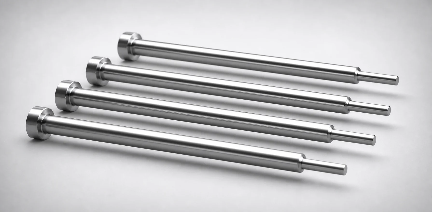
M2 Steel Taperless One-Step Center Pins
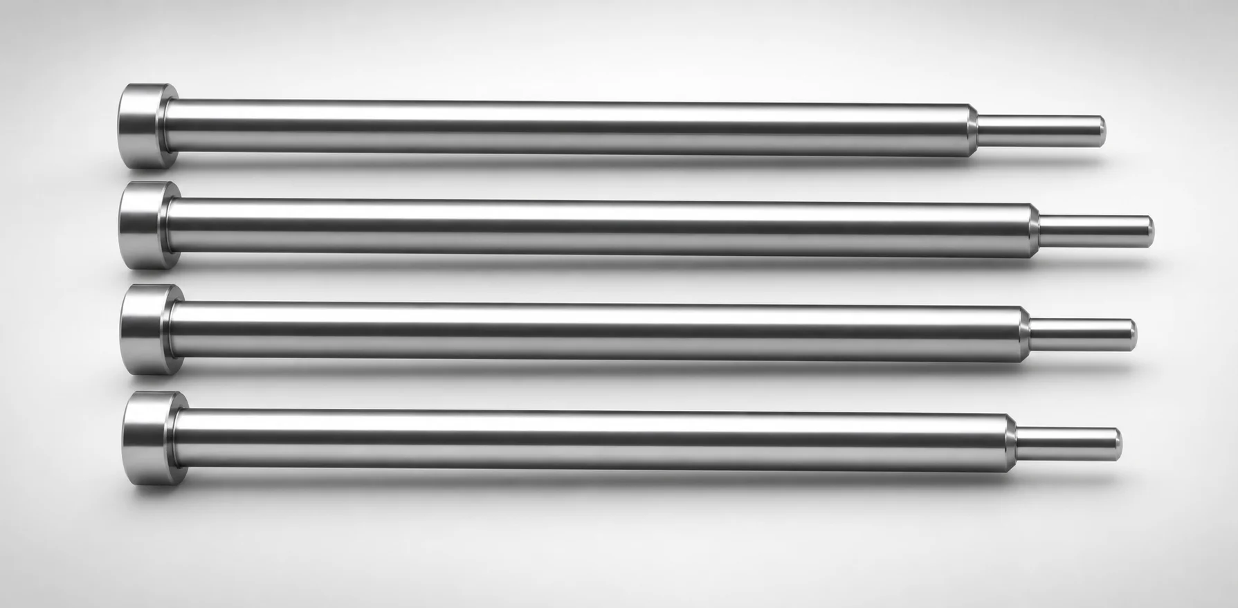
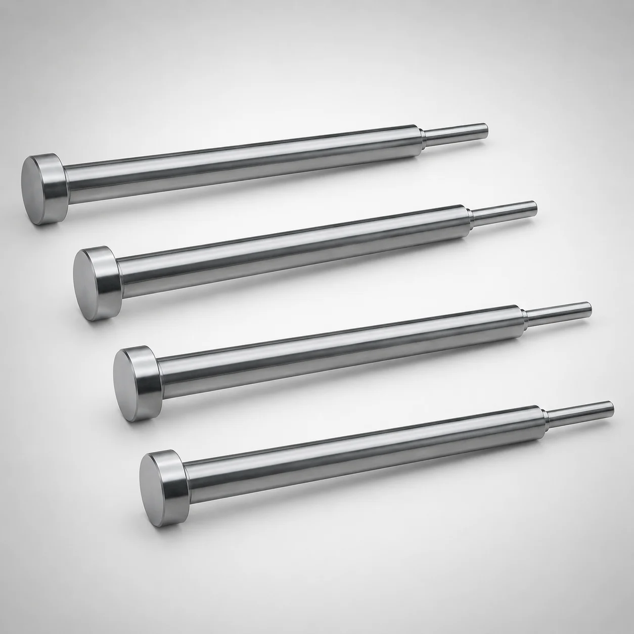
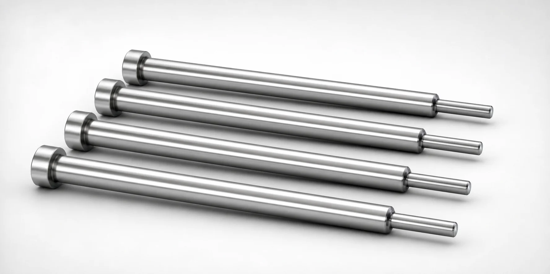
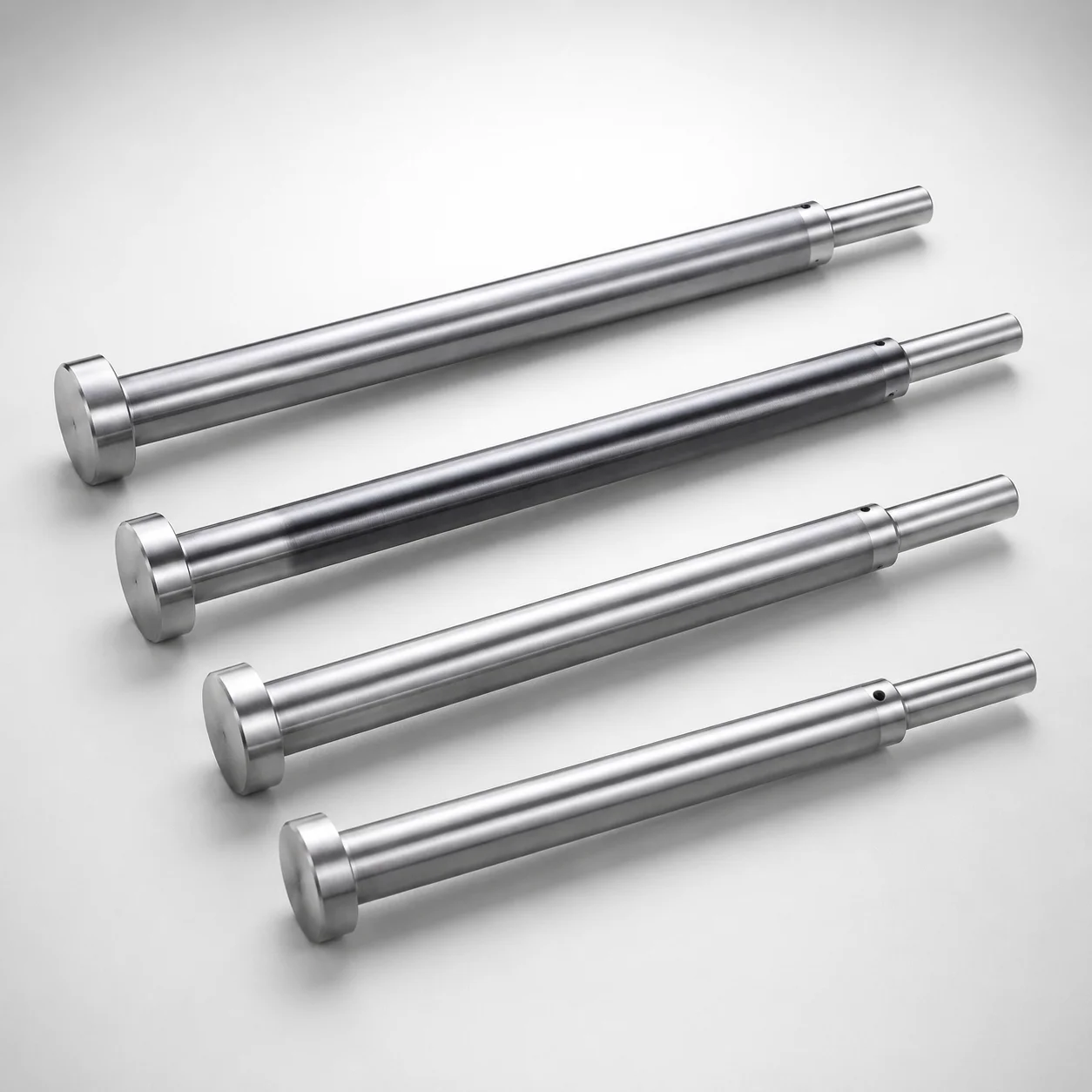
Taperless one-step center pins (M2 steel) provide reliable work positioning without a taper, improving repeatability in machining and setup. The one-step design supports consistent center engagement while using configurable shaft sizes for different tool layouts.
- One-step, taperless center geometry for stable alignment and repeatable positioning
- Constructed from M2 steel for dependable wear resistance in production environments
- Configurable shaft diameter/length options to match sleeve, guide, and machining requirements
- Suitable for center locating in industrial machining, jigs, and precision tooling
Specifications
2412 configurations available
| Head Thickness | Shaft Diameter Tolerance | D/P (Shaft Diameter) (mm) | Step Shape | Tip Shape | Compatible Sleeve Hole Diameter Tolerance | No. (Nominal diameter) (mm) | Precision group | A (Tip part) (mm) | C (Tip part) (mm) | F (Shaft diameter length) (mm) | G (Tip C chamfering width on the tip part) (mm) | K (Tip part angle) (°) | L (L dimension) (mm) | Q (Tip R chamfering on the tip part) (mm) | R (Tip part) (mm) | S (Tip tapered width on the tip part) (mm) | type |
|---|---|---|---|---|---|---|---|---|---|---|---|---|---|---|---|---|---|
| 4mm(T4) | 0/-0.005 | 0.8 ~ 0.99 | B | No processing | +0.005/0 | 1 | Standard | 0.5 ~ 0.99 | - | 50 ~ 149.5 | - | - | 70 ~ 200 | - | - | - | - |
| 4mm(T4) | 0/-0.005 | 1 ~ 1.49 | B | No processing | +0.005/0 | 1.5 | Standard | 0.5 ~ 1.49 | - | 50 ~ 246.5 | - | - | 70 ~ 250 | - | - | - | - |
| 4mm(T4) | 0/-0.005 | 1.5 ~ 1.99 | B | No processing | +0.005/0 | 2 | Standard | 0.7 ~ 1.98 | - | 50 ~ 249.3 | - | - | 70 ~ 250 | - | - | - | - |
| 4mm(T4) | 0/-0.005 | 2 ~ 2.49 | B | No processing | +0.005/0 | 2.5 | Standard | 0.7 ~ 2.48 | - | 50 ~ 249.3 | - | - | 70 ~ 250 | - | - | - | - |
| 4mm(T4) | 0/-0.005 | 2.5 ~ 2.99 | B | No processing | +0.005/0 | 3 | Standard | 1 ~ 2.98 | - | 50 ~ 299.3 | - | - | 70 ~ 300 | - | - | - | - |
| 4mm(T4) | 0/-0.005 | 3 ~ 3.49 | B | No processing | +0.005/0 | 3.5 | Standard | 1 ~ 3.48 | - | 50 ~ 299.3 | - | - | 70 ~ 300 | - | - | - | - |
| 4mm(T4) | 0/-0.005 | 3.5 ~ 3.99 | B | No processing | +0.005/0 | 4 | Standard | 1 ~ 3.98 | - | 50 ~ 299.3 | - | - | 70 ~ 300 | - | - | - | - |
| 4mm(T4) | 0/-0.005 | 4 ~ 4.49 | B | No processing | +0.005/0 | 4.5 | Standard | 1.5 ~ 4.48 | - | 50 ~ 295.3 | - | - | 70 ~ 300 | - | - | - | - |
| 4mm(T4) | 0/-0.005 | 4.5 ~ 4.99 | B | No processing | +0.005/0 | 5 | Standard | 1.5 ~ 4.98 | - | 50 ~ 349.5 | - | - | 70 ~ 350 | - | - | - | - |
| 4mm(T4) | 0/-0.005 | 5 ~ 5.49 | B | No processing | +0.005/0 | 5.5 | Standard | 2 ~ 5.48 | - | 50 ~ 349.3 | - | - | 70 ~ 350 | - | - | - | - |
| 4mm(T4) | 0/-0.005 | 5.5 ~ 5.99 | B | No processing | +0.005/0 | 6 | Standard | 2 ~ 5.98 | - | 50 ~ 349.3 | - | - | 70 ~ 350 | - | - | - | - |
| 4mm(T4) | 0/-0.005 | 6 ~ 6.49 | B | No processing | +0.005/0 | 6.5 | Standard | 2 ~ 6.48 | - | 50 ~ 349.5 | - | - | 70 ~ 350 | - | - | - | - |
| 4mm(T4) | 0/-0.005 | 6.5 ~ 6.99 | B | No processing | +0.005/0 | 7 | Standard | 2 ~ 6.98 | - | 50 ~ 349.3 | - | - | 70 ~ 350 | - | - | - | - |
| 4mm(T4) | 0/-0.005 | 7 ~ 7.99 | B | No processing | +0.005/0 | 8 | Standard | 2 ~ 7.98 | - | 50 ~ 349.3 | - | - | 70 ~ 350 | - | - | - | - |
| 4mm(T4) | 0/-0.005 | 8 ~ 9.99 | B | No processing | +0.005/0 | 10 | Standard | 2 ~ 9.99 | - | 50 ~ 349.5 | - | - | 70 ~ 350 | - | - | - | - |
| 4mm(T4) | 0/-0.005 | 10 ~ 11.99 | B | No processing | +0.005/0 | 12 | Standard | 2 ~ 11.99 | - | 50 ~ 349.5 | - | - | 70 ~ 350 | - | - | - | - |
| 4mm(T4) | 0/-0.005 | 1 ~ 1.49 | B | B | +0.005/0 | 1.5 | Standard | 0.5 ~ 1.49 | - | 50 ~ 249.5 | - | - | 70 ~ 250 | - | - | - | - |
| 4mm(T4) | 0/-0.005 | 1.5 ~ 1.99 | B | B | +0.005/0 | 2 | Standard | 0.7 ~ 1.99 | - | 50 ~ 249.5 | - | - | 70 ~ 250 | - | - | - | - |
| 4mm(T4) | 0/-0.005 | 2 ~ 2.49 | B | B | +0.005/0 | 2.5 | Standard | 0.7 ~ 2.49 | - | 50 ~ 249.5 | - | - | 70 ~ 250 | - | - | - | - |
| 4mm(T4) | 0/-0.005 | 2.5 ~ 2.99 | B | B | +0.005/0 | 3 | Standard | 1 ~ 2.99 | - | 50 ~ 299.5 | - | - | 70 ~ 300 | - | - | - | - |
| 4mm(T4) | 0/-0.005 | 3 ~ 3.49 | B | B | +0.005/0 | 3.5 | Standard | 1 ~ 3.49 | - | 50 ~ 299.5 | - | - | 70 ~ 300 | - | - | - | - |
| 4mm(T4) | 0/-0.005 | 3.5 ~ 3.99 | B | B | +0.005/0 | 4 | Standard | 1 ~ 3.99 | - | 50 ~ 299.5 | - | - | 70 ~ 300 | - | - | - | - |
| 4mm(T4) | 0/-0.005 | 4 ~ 4.49 | B | B | +0.005/0 | 4.5 | Standard | 1.5 ~ 4.49 | - | 50 ~ 299.5 | - | - | 70 ~ 300 | - | - | - | - |
| 4mm(T4) | 0/-0.005 | 4.5 ~ 4.99 | B | B | +0.005/0 | 5 | Standard | 1.5 ~ 4.99 | - | 50 ~ 349.5 | - | - | 70 ~ 350 | - | - | - | - |
| 4mm(T4) | 0/-0.005 | 5 ~ 5.49 | B | B | +0.005/0 | 5.5 | Standard | 1.5 ~ 5.49 | - | 50 ~ 349.5 | - | - | 70 ~ 350 | - | - | - | - |
| 4mm(T4) | 0/-0.005 | 5.5 ~ 5.99 | B | B | +0.005/0 | 6 | Standard | 2 ~ 5.99 | - | 50 ~ 349.5 | - | - | 70 ~ 350 | - | - | - | - |
| 4mm(T4) | 0/-0.005 | 6 ~ 6.49 | B | B | +0.005/0 | 6.5 | Standard | 2 ~ 6.49 | - | 50 ~ 349.5 | - | - | 70 ~ 350 | - | - | - | - |
| 4mm(T4) | 0/-0.005 | 6.5 ~ 6.99 | B | B | +0.005/0 | 7 | Standard | 2 ~ 6.99 | - | 50 ~ 349.5 | - | - | 70 ~ 350 | - | - | - | - |
| 4mm(T4) | 0/-0.005 | 7 ~ 7.99 | B | B | +0.005/0 | 8 | Standard | 2 ~ 7.99 | - | 50 ~ 349.5 | - | - | 70 ~ 350 | - | - | - | - |
| 4mm(T4) | 0/-0.005 | 8 ~ 9.99 | B | B | +0.005/0 | 10 | Standard | 2 ~ 9.99 | - | 50 ~ 349.5 | - | - | 70 ~ 350 | - | - | - | - |
| 4mm(T4) | 0/-0.005 | 10 ~ 11.99 | B | B | +0.005/0 | 12 | Standard | 2 ~ 11.99 | - | 50 ~ 349.5 | - | - | 70 ~ 350 | - | - | - | - |
| 4mm(T4) | 0/-0.005 | 1 ~ 1.49 | B | C | +0.005/0 | 1.5 | Standard | 0.5 ~ 1.49 | - | 50 ~ 249.5 | 0.1 ~ 0.7 | - | 70 ~ 250 | - | - | - | - |
| 4mm(T4) | 0/-0.005 | 1.5 ~ 1.99 | B | C | +0.005/0 | 2 | Standard | 0.7 ~ 1.99 | - | 50 ~ 249.5 | 0.1 ~ 0.9 | - | 70 ~ 250 | - | - | - | - |
| 4mm(T4) | 0/-0.005 | 2 ~ 2.49 | B | C | +0.005/0 | 2.5 | Standard | 0.7 ~ 2.49 | - | 50 ~ 249.5 | 0.1 ~ 1.2 | - | 70 ~ 250 | - | - | - | - |
| 4mm(T4) | 0/-0.005 | 2.5 ~ 2.99 | B | C | +0.005/0 | 3 | Standard | 1 ~ 2.99 | - | 50 ~ 299.5 | 0.1 ~ 1.4 | - | 70 ~ 300 | - | - | - | - |
| 4mm(T4) | 0/-0.005 | 3 ~ 3.49 | B | C | +0.005/0 | 3.5 | Standard | 1 ~ 3.49 | - | 50 ~ 299.5 | 0.1 ~ 1.7 | - | 70 ~ 300 | - | - | - | - |
| 4mm(T4) | 0/-0.005 | 3.5 ~ 3.99 | B | C | +0.005/0 | 4 | Standard | 1 ~ 3.99 | - | 50 ~ 299.5 | 0.1 ~ 1.9 | - | 70 ~ 300 | - | - | - | - |
| 4mm(T4) | 0/-0.005 | 4 ~ 4.49 | B | C | +0.005/0 | 4.5 | Standard | 1.5 ~ 4.49 | - | 50 ~ 299.5 | 0.1 ~ 2.2 | - | 70 ~ 300 | - | - | - | - |
| 4mm(T4) | 0/-0.005 | 4.5 ~ 4.99 | B | C | +0.005/0 | 5 | Standard | 1.5 ~ 4.99 | - | 50 ~ 349.5 | 0.1 ~ 2.4 | - | 70 ~ 350 | - | - | - | - |
| 4mm(T4) | 0/-0.005 | 5 ~ 5.49 | B | C | +0.005/0 | 5.5 | Standard | 1.5 ~ 5.49 | - | 50 ~ 349.5 | 0.1 ~ 2.7 | - | 70 ~ 350 | - | - | - | - |
| 4mm(T4) | 0/-0.005 | 5.5 ~ 5.99 | B | C | +0.005/0 | 6 | Standard | 2 ~ 5.99 | - | 50 ~ 349.5 | 0.1 ~ 2.9 | - | 70 ~ 350 | - | - | - | - |
| 4mm(T4) | 0/-0.005 | 6 ~ 6.49 | B | C | +0.005/0 | 6.5 | Standard | 2 ~ 6.49 | - | 50 ~ 349.5 | 0.1 ~ 3.2 | - | 70 ~ 350 | - | - | - | - |
| 4mm(T4) | 0/-0.005 | 6.5 ~ 6.99 | B | C | +0.005/0 | 7 | Standard | 2 ~ 6.99 | - | 50 ~ 349.5 | 0.1 ~ 3.4 | - | 70 ~ 350 | - | - | - | - |
| 4mm(T4) | 0/-0.005 | 7 ~ 7.99 | B | C | +0.005/0 | 8 | Standard | 2 ~ 7.99 | - | 50 ~ 349.5 | 0.1 ~ 3.9 | - | 70 ~ 350 | - | - | - | - |
| 4mm(T4) | 0/-0.005 | 8 ~ 9.99 | B | C | +0.005/0 | 10 | Standard | 2 ~ 9.99 | - | 50 ~ 349.5 | 0.1 ~ 4.9 | - | 70 ~ 350 | - | - | - | - |
| 4mm(T4) | 0/-0.005 | 10 ~ 11.99 | B | C | +0.005/0 | 12 | Standard | 2 ~ 11.99 | - | 50 ~ 349.5 | 0.1 ~ 6.4 | - | 70 ~ 350 | - | - | - | - |
| 4mm(T4) | 0/-0.005 | 1 ~ 1.49 | B | G | +0.005/0 | 1.5 | Standard | 0.5 ~ 1.49 | - | 50 ~ 249.5 | - | 21 ~ 60 | 70 ~ 250 | - | - | - | - |
| 4mm(T4) | 0/-0.005 | 1.5 ~ 1.99 | B | G | +0.005/0 | 2 | Standard | 0.7 ~ 1.99 | - | 50 ~ 249.5 | - | 21 ~ 60 | 70 ~ 250 | - | - | - | - |
| 4mm(T4) | 0/-0.005 | 2 ~ 2.49 | B | G | +0.005/0 | 2.5 | Standard | 0.7 ~ 2.49 | - | 50 ~ 249.5 | - | 21 ~ 60 | 70 ~ 250 | - | - | - | - |
| 4mm(T4) | 0/-0.005 | 2.5 ~ 2.99 | B | G | +0.005/0 | 3 | Standard | 1 ~ 2.99 | - | 50 ~ 299.5 | - | 21 ~ 60 | 70 ~ 300 | - | - | - | - |
Product Guide
Application Scenarios+
Where it’s used: These taperless one-step center pins are installed in precision mold and tooling assemblies to set and verify part positioning during machining, and they can also be used as locating references in injection mold build-ups where repeatable center engagement matters.
- Automotive connector housings (tooling alignment): Pairing the one-step, taperless geometry with a matching sleeve hole tolerance helps maintain stable center location when switching setups or rework stages.
- Medical device component machining (precision repeatability): The taperless engagement reduces sensitivity to taper-related misalignment, supporting consistent center alignment for housings and small internal features.
- Industrial jigs and precision fixtures (setup verification): Use the configurable shaft diameter/length range to match the sleeve, guide, and cavity/core locating requirements in your specific tooling layout.
Why this variant fits: M2 steel provides dependable wear resistance for repeated insertion cycles, while the one-step taperless tip geometry is designed for consistent center contact without the positional variation that can occur with tapered features.
Material & Process Details+
Steel grade and intent: This component is supplied as M2 steel. In tooling practice, M2 is commonly selected for its strong balance of hardness and wear resistance for locating and guidance applications where repeated contact occurs.
- Wear vs. toughness trade-off: M2’s high hardness supports abrasion resistance at the tip and engagement surfaces, but it requires correct heat treatment and proper handling to avoid brittleness in thin sections.
- Manufacturing process (typical for this class): Blank forming/turning followed by heat treatment (quench-and-temper in practice for high-speed steels), then finishing to meet the specified shaft tolerance and sleeve compatibility.
- Hardness: The exact HRC value is not provided in the supplied data, so it should be verified against the material certificate for your configured size.
Heat treatment state: Verify the delivered condition (pre-hardened vs. quenched & tempered / tempered hard state) for your selected specification, since hardness directly affects wear resistance and the fit behavior with sleeve hole tolerances.
Sizing & Selection Guide+
Step 1: Select by nominal diameter and shaft range. Choose the Nominal diameter (No.) 1 ~ 12 mm and the corresponding shaft diameter (D/P) 0.8 ~ 10 mm so it matches the locating function in your sleeve/guide system.
- Shaft diameter tolerance: Confirm the pin shaft meets the provided tolerance group (e.g., 0/-0.005, -0.01/-0.02) to achieve the intended clearance/interference behavior.
- Sleeve hole compatibility: Match against the compatible sleeve hole diameter tolerance: +0.005/0, +0.01/0, or H7. This is the primary determinant of whether the pin will seat smoothly or with controlled resistance.
Step 2: Match length and head geometry. Select the correct L (70 ~ 200 / 250 / 300 / 350 mm options) for the stack-up depth and choose Head Thickness (T4 / JIS 6 / JIS 8) to support proper seating in the assembly.
- Configure the one-step geometry: Use the available Step Shape (B, C, D, E) and Tip Shape options (No processing, B, C, G, R, T) to suit your sleeve counter features and center engagement requirement.
Tolerance/fit note: Because the shaft tolerance and sleeve hole tolerance are both specified, dimension the locating interface first; then verify the tip/taper features (A/C/R/G, K angle) to ensure consistent center contact.
Frequently Asked Questions
How do I choose the correct shaft diameter (D/P) and nominal diameter (No.) for this taperless one-step center pin?+
Select No. (nominal diameter) 1 ~ 12 mm and ensure the corresponding shaft diameter D/P 0.8 ~ 10 mm matches your sleeve/guide design. Then verify the shaft diameter tolerance option (e.g., 0/-0.005 or -0.01/-0.02) so the fit matches your intended locating behavior.
What sleeve hole tolerance should I use to get a controlled fit with this pin?+
This product lists compatible sleeve hole diameter tolerance options of +0.005/0, +0.01/0, or H7. Pair the sleeve hole tolerance with the pin’s shaft diameter tolerance to achieve the clearance or seating behavior your tooling requires. For repeatable location, treat this interface as the primary sizing/fit check.
Which head thickness and overall length (L) options fit typical mold build-up stack-ups?+
Use Head Thickness choices of 4 mm (T4), 6 mm (JIS), or 8 mm (JIS) to match the seating surface thickness in your tooling. Then choose the appropriate L dimension from 70 ~ 200, 70 ~ 250, 70 ~ 300, or 70 ~ 350 mm to cover the stack depth without bottoming out.
How do step shape and tip shape affect center engagement for taperless locating?+
Center engagement is controlled by the Step Shape (B, C, D, E) and the Tip Shape option (including No processing, B, C, G, R, T). Use these to match your sleeve counter features and the required center contact profile, since the taperless one-step geometry relies on the selected step/tip contact for stable alignment.
What tip geometry parameters should I verify during sizing (A, C, R, K, and chamfers)?+
Confirm the selected A (0.5 ~ 2 mm), C (0.1 ~ 1.5 mm or 0.1 ~ 1 mm), and R (0.2 ~ 0.3 mm) values, along with K tip angle (21 ~ 60° or 21 ~ 45°). Also verify chamfer widths such as G (0.1 ~ 0.5 mm) and Q (0.2 ~ 0.2 mm), since these influence how the tip seats into the center interface.
Related Products
Need Custom Specifications?
Our engineering team can help with custom configurations, material selection, and volume pricing.