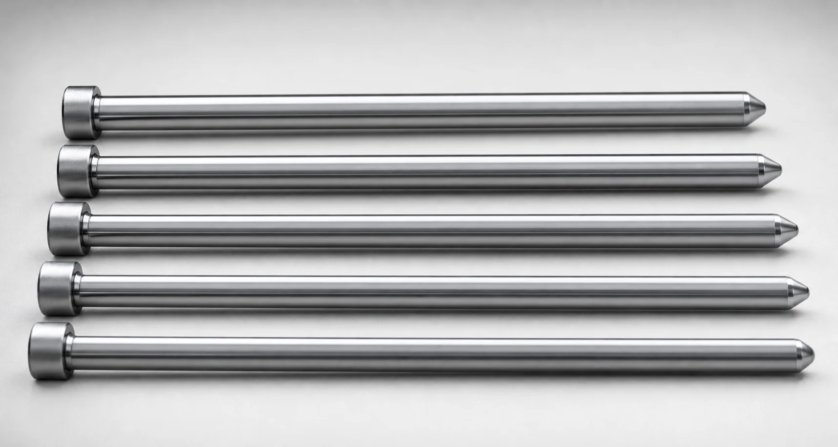
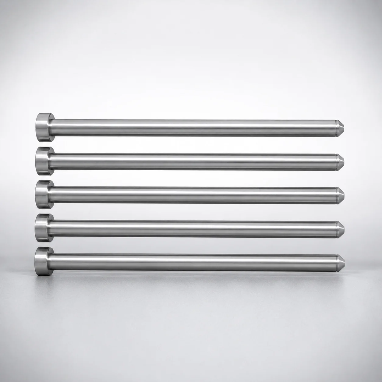
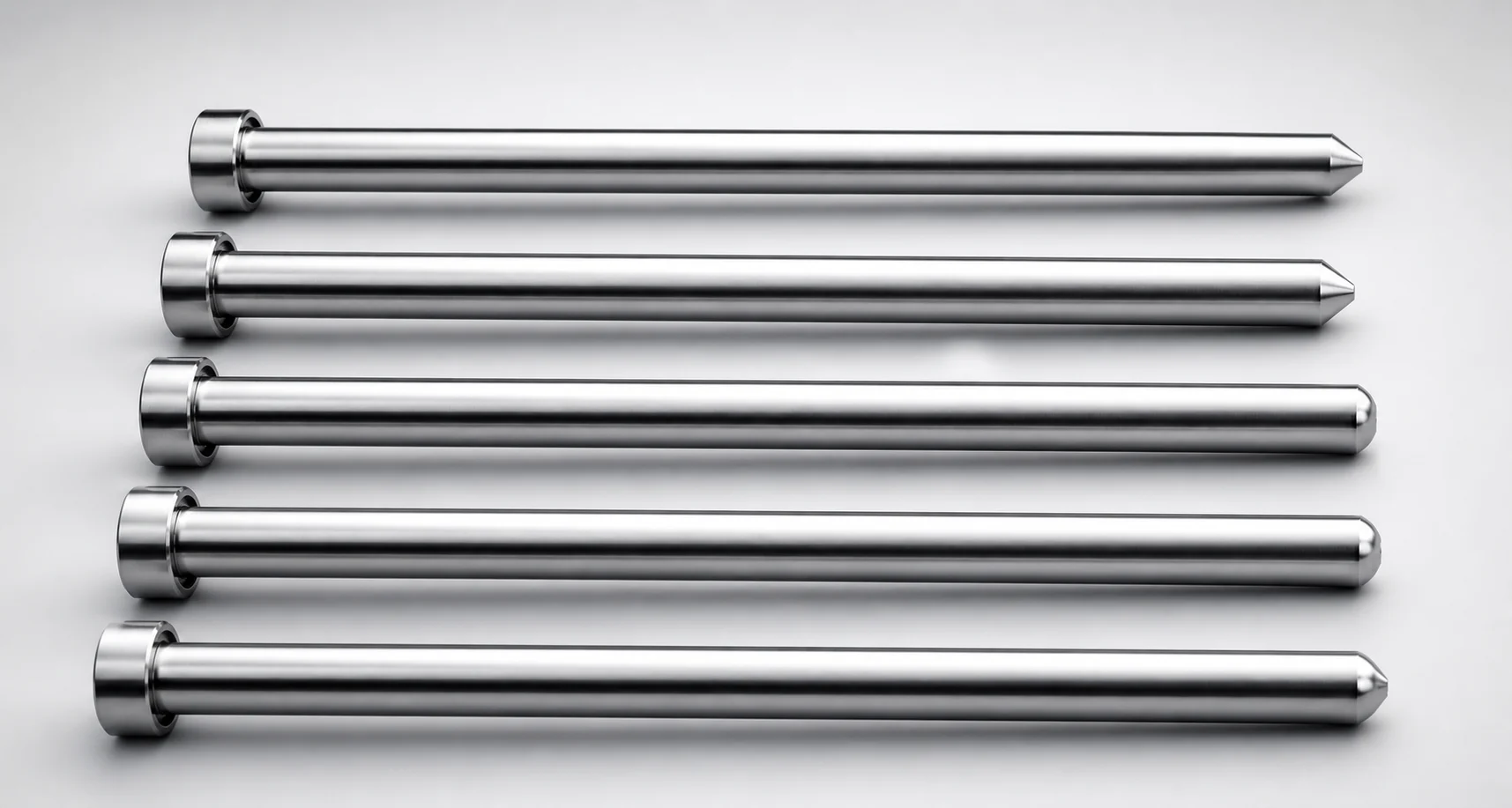
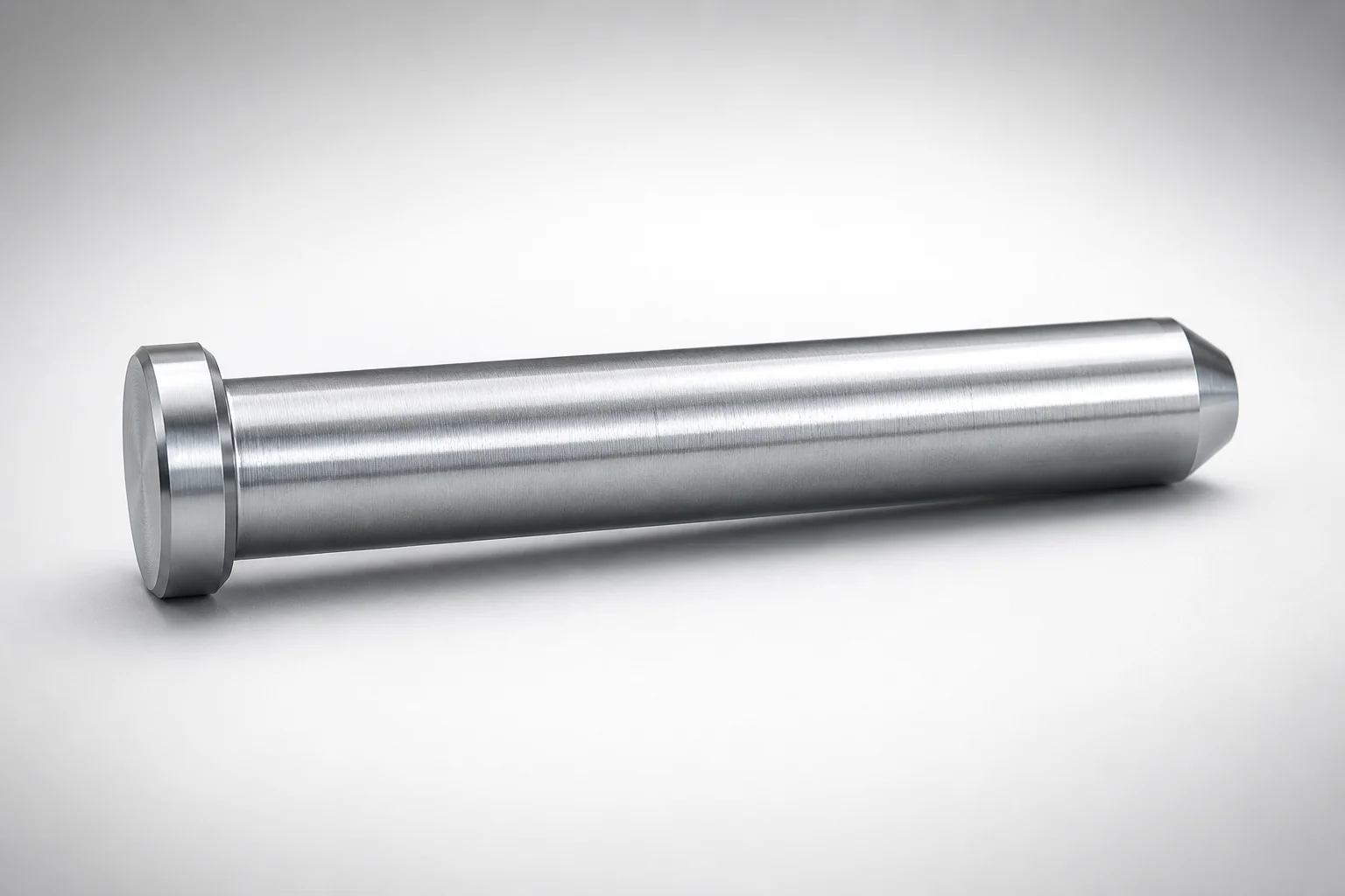
JIS Standard SKD61 Steel Straight Center Pins with Tip, Nitrided
Straight center pins with tip (SKD61 steel) use a nitrided surface for controlled wear, supporting consistent centering during mold closing and part ejection. The tip-process design helps locate components accurately at setup and in production.
- Tip-processed geometry supports reliable centering for die alignment and repeated assembly
- Nitrided SKD61 steel construction improves surface durability in cycle-heavy molds
- Selectable shaft diameter with reference tolerance supports stable fit in ejector sleeve systems
- JIS manufactured center pins suited for precision mold applications
Specifications
135 configurations available
| Head Thickness | Shaft Diameter Tolerance | D/P (Shaft Diameter) (mm) | Tip Shape | C (C chamfering width on the tip) (mm) | K (Taper angle) (°) | L (L dimension) (mm) | R (Tip R chamfering) (mm) | S (Tip tapered width) (mm) | type |
|---|---|---|---|---|---|---|---|---|---|
| 6mm(JIS) | -0.01/-0.02 | 4 | B | - | - | 50 ~ 500 | - | - | - |
| 6mm(JIS) | -0.01/-0.02 | 4.5 | B | - | - | 50 ~ 500 | - | - | - |
| 6mm(JIS) | -0.01/-0.02 | 5 | B | - | - | 50 ~ 500 | - | - | - |
| 6mm(JIS) | -0.01/-0.02 | 5.5 | B | - | - | 50 ~ 500 | - | - | - |
| 6mm(JIS) | -0.01/-0.02 (Reference tolerance) | 6 | B | - | - | 50 ~ 600 | - | - | - |
| 6mm(JIS) | -0.01/-0.02 (Reference tolerance) | 6.5 | B | - | - | 50 ~ 600 | - | - | - |
| 6mm(JIS) | -0.01/-0.02 (Reference tolerance) | 7 | B | - | - | 50 ~ 600 | - | - | - |
| 8mm(JIS) | -0.01/-0.02 (Reference tolerance) | 8 | B | - | - | 50 ~ 600 | - | - | - |
| 8mm(JIS) | -0.01/-0.02 (Reference tolerance) | 10 | B | - | - | 50 ~ 600 | - | - | - |
| 8mm(JIS) | -0.01/-0.02 (Reference tolerance) | 12 | B | - | - | 50 ~ 700 | - | - | - |
| 8mm(JIS) | -0.01/-0.02 (Reference tolerance) | 15 | B | - | - | 50 ~ 700 | - | - | - |
| 8mm(JIS) | -0.01/-0.02 (Reference tolerance) | 16 | B | - | - | 50 ~ 700 | - | - | - |
| 6mm(JIS) | -0.01/-0.02 | 4 | C | 0.1 ~ 1.9 | - | 50 ~ 500 | - | - | - |
| 6mm(JIS) | -0.01/-0.02 | 4.5 | C | 0.1 ~ 2.1 | - | 50 ~ 500 | - | - | - |
| 6mm(JIS) | -0.01/-0.02 | 5 | C | 0.1 ~ 2.4 | - | 50 ~ 500 | - | - | - |
| 6mm(JIS) | -0.01/-0.02 | 5.5 | C | 0.1 ~ 2.6 | - | 50 ~ 500 | - | - | - |
| 6mm(JIS) | -0.01/-0.02 (Reference tolerance) | 6 | C | 0.1 ~ 2.9 | - | 50 ~ 600 | - | - | - |
| 6mm(JIS) | -0.01/-0.02 (Reference tolerance) | 6.5 | C | 0.1 ~ 3.1 | - | 50 ~ 600 | - | - | - |
| 6mm(JIS) | -0.01/-0.02 (Reference tolerance) | 7 | C | 0.1 ~ 3.4 | - | 50 ~ 600 | - | - | - |
| 8mm(JIS) | -0.01/-0.02 (Reference tolerance) | 8 | C | 0.1 ~ 3.9 | - | 50 ~ 600 | - | - | - |
| 8mm(JIS) | -0.01/-0.02 (Reference tolerance) | 10 | C | 0.1 ~ 4.9 | - | 50 ~ 600 | - | - | - |
| 8mm(JIS) | -0.01/-0.02 (Reference tolerance) | 12 | C | 0.1 ~ 5.9 | - | 50 ~ 700 | - | - | - |
| 8mm(JIS) | -0.01/-0.02 (Reference tolerance) | 15 | C | 0.1 ~ 7.4 | - | 50 ~ 700 | - | - | - |
| 8mm(JIS) | -0.01/-0.02 (Reference tolerance) | 16 | C | 0.1 ~ 7.9 | - | 50 ~ 700 | - | - | - |
| 6mm(JIS) | -0.01/-0.02 | 4 | G | - | 45 ~ 89 | 50 ~ 500 | - | - | - |
| 6mm(JIS) | -0.01/-0.02 | 4.5 | G | - | 45 ~ 89 | 50 ~ 500 | - | - | - |
| 6mm(JIS) | -0.01/-0.02 | 5 | G | - | 45 ~ 89 | 50 ~ 500 | - | - | - |
| 6mm(JIS) | -0.01/-0.02 | 5.5 | G | - | 45 ~ 89 | 50 ~ 500 | - | - | - |
| 6mm(JIS) | -0.01/-0.02 (Reference tolerance) | 6 | G | - | 45 ~ 89 | 50 ~ 600 | - | - | - |
| 6mm(JIS) | -0.01/-0.02 (Reference tolerance) | 6.5 | G | - | 45 ~ 89 | 50 ~ 600 | - | - | - |
| 6mm(JIS) | -0.01/-0.02 (Reference tolerance) | 7 | G | - | 1 ~ 45 | 50 ~ 600 | - | - | - |
| 8mm(JIS) | -0.01/-0.02 (Reference tolerance) | 8 | G | - | 45 ~ 89 | 50 ~ 600 | - | - | - |
| 8mm(JIS) | -0.01/-0.02 (Reference tolerance) | 10 | G | - | 45 ~ 89 | 50 ~ 600 | - | - | - |
| 8mm(JIS) | -0.01/-0.02 (Reference tolerance) | 12 | G | - | 45 ~ 89 | 50 ~ 700 | - | - | - |
| 8mm(JIS) | -0.01/-0.02 (Reference tolerance) | 15 | G | - | 45 ~ 89 | 50 ~ 700 | - | - | - |
| 8mm(JIS) | -0.01/-0.02 (Reference tolerance) | 16 | G | - | 45 ~ 89 | 50 ~ 700 | - | - | - |
| 6mm(JIS) | -0.01/-0.02 | 4 | R | - | - | 50 ~ 500 | 0.2 ~ 1.9 | - | - |
| 6mm(JIS) | -0.01/-0.02 | 4.5 | R | - | - | 50 ~ 500 | 0.2 ~ 2.1 | - | - |
| 6mm(JIS) | -0.01/-0.02 | 5 | R | - | - | 50 ~ 500 | 0.2 ~ 2.4 | - | - |
| 6mm(JIS) | -0.01/-0.02 | 5.5 | R | - | - | 50 ~ 500 | 0.2 ~ 2.6 | - | - |
| 6mm(JIS) | -0.01/-0.02 (Reference tolerance) | 6 | R | - | - | 50 ~ 600 | 0.2 ~ 2.9 | - | - |
| 6mm(JIS) | -0.01/-0.02 (Reference tolerance) | 6.5 | R | - | - | 50 ~ 600 | 0.2 ~ 3.1 | - | - |
| 6mm(JIS) | -0.01/-0.02 (Reference tolerance) | 7 | R | - | - | 50 ~ 600 | 0.2 ~ 3.4 | - | - |
| 8mm(JIS) | -0.01/-0.02 (Reference tolerance) | 8 | R | - | - | 50 ~ 600 | 0.2 ~ 3.9 | - | - |
| 8mm(JIS) | -0.01/-0.02 (Reference tolerance) | 10 | R | - | - | 50 ~ 600 | 0.2 ~ 4.9 | - | - |
| 8mm(JIS) | -0.01/-0.02 (Reference tolerance) | 12 | R | - | - | 50 ~ 700 | 0.2 ~ 5.9 | - | - |
| 8mm(JIS) | -0.01/-0.02 (Reference tolerance) | 15 | R | - | - | 50 ~ 700 | 0.2 ~ 7.4 | - | - |
| 8mm(JIS) | -0.01/-0.02 (Reference tolerance) | 16 | R | - | - | 50 ~ 700 | 0.2 ~ 7.9 | - | - |
| 6mm(JIS) | -0.01/-0.02 | 4 | T | - | 1 ~ 45 | 50 ~ 500 | - | 0.1 ~ 8 | - |
| 6mm(JIS) | -0.01/-0.02 | 4.5 | T | - | 1 ~ 45 | 50 ~ 500 | - | 0.1 ~ 9 | - |
Product Guide
Application Scenarios+
Straight center pins with tip are used in injection mold tooling to ensure repeatable alignment between moving die components and the ejector-side interfaces during every cycle. The nitrided SKD61 steel surface helps maintain dimensional stability and wear resistance in high-count molds where centering accuracy must remain consistent over time.
- In automotive connector molds, the tip geometry supports controlled location during mold closure, reducing misalignment risk and improving part-to-cavity consistency.
- For consumer electronics housings, the pin tip is used to register ejector sleeves and guide smooth ejection, where cycle-heavy operation demands durable surface performance.
- In medical device housings and precision inserts, the reference/locating function improves setup repeatability, helping maintain stable positioning between assembly cycles.
Because this variant specifies JIS SKD61 with nitriding, it is suited for long-running die sets that prioritize alignment reliability and reduced tip wear under frequent mechanical contact.
Material & Process Details+
This product uses JIS SKD61 steel, a hot-work die steel commonly selected for tooling requiring toughness under repeated thermal and mechanical loading. The nitrided surface treatment improves wear resistance at the tip/contact area while keeping the bulk steel properties suitable for shock tolerance during mold operations.
- Heat treatment state: nitrided (surface-treated) SKD61, providing a hard, wear-resistant top layer.
- Hardness & trade-offs: nitriding increases surface hardness and abrasion durability, while the core remains more impact-tolerant than a fully hardened, uniformly very high-hardness state.
- Wear vs toughness: optimized for repeated contact and sliding/locating at the tip; performance prioritizes surface durability with acceptable toughness for ejector alignment tasks.
Compared with non-nitrided tool steels, the nitrided SKD61 variant typically offers longer service life at the locating surface where wear would otherwise accumulate.
Sizing & Selection Guide+
Select the center pin size to match the ejector sleeve and die locating requirements using the provided ranges for shaft diameter and overall length. The D/P (shaft diameter) is 1.5 ~ 16 mm; choose the diameter that matches the sleeve bore/guide feature so the reference tolerance can be maintained for stable fit.
- Confirm shaft diameter tolerance: -0.01 / -0.02 (reference tolerance). This indicates how tight the fit must be relative to the mating bore.
- Choose L (length) based on the required projection and engagement depth: available options include 50~500, 50~600, 50~700, 50~250, and 50~400 mm.
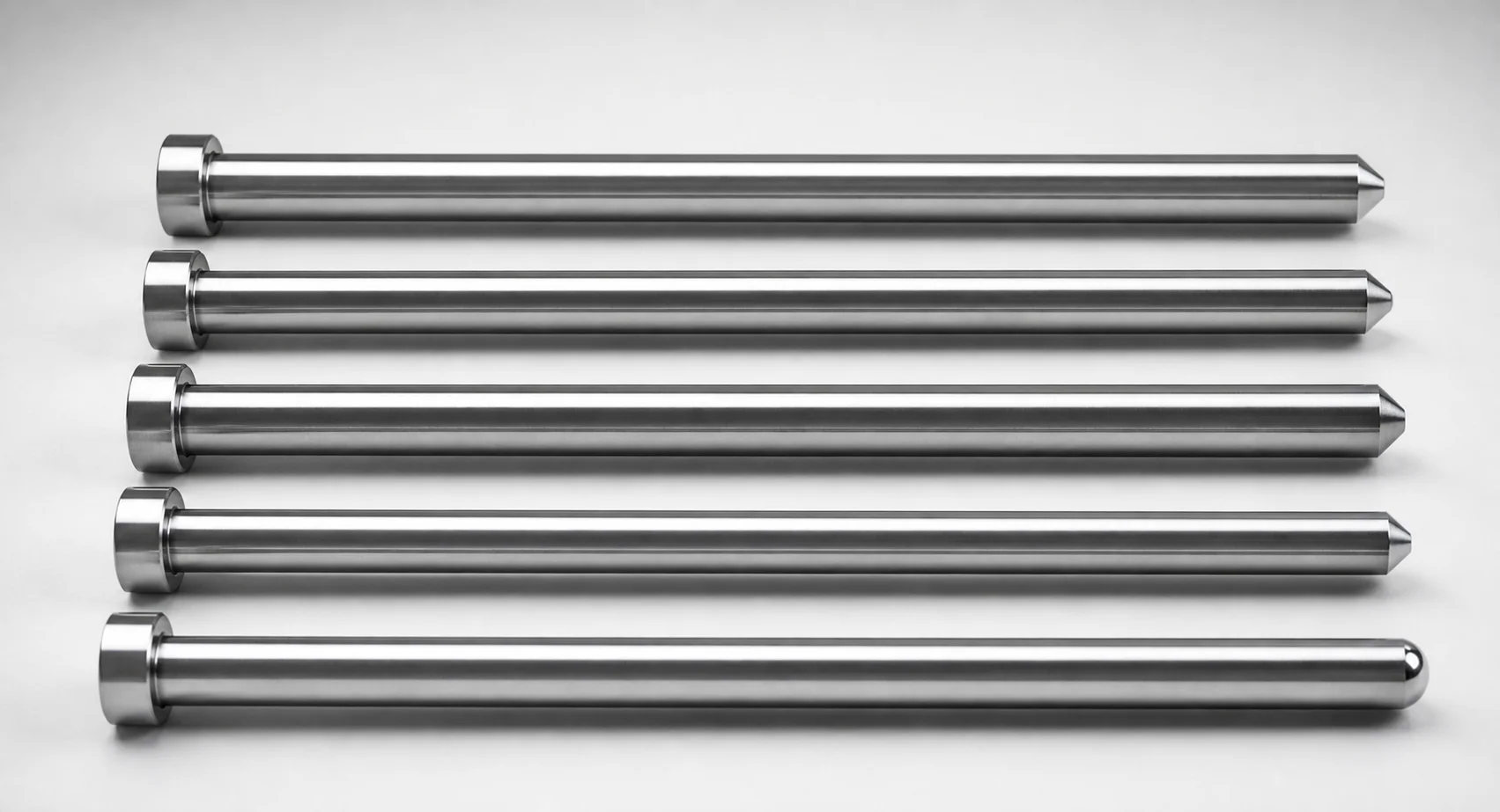
- Select tip shape and geometry to match your registration method: B, C, G, R, T. Tip chamfering parameters are C = 0.1 (0.1~0.1), R = 0.2 (0.2~0.2), S = 0.1 (0.1~0.1), and taper angle K = 45~89° or 1~45°.
Also verify head thickness per the JIS configuration (6 mm or 8 mm) or T4 = 4 mm, since head size affects seating and assembly alignment.
Frequently Asked Questions
Which tip shapes (B/C/G/R/T) are suitable for die-to-sleeve centering when using a nitrided SKD61 straight center pin?+
What shaft diameter range and reference tolerance should I use to achieve a stable fit in the ejector sleeve system?+
How do I choose the correct length (L) for proper engagement without interfering with the mold during ejection?+
What does nitrided SKD61 change for wear at the locating tip compared with an untreated tool-steel surface?+
Which head thickness (4 mm / 6 mm / 8 mm) should be selected for correct seating in the mold layout?+
Related Products
Need Custom Specifications?
Our engineering team can help with custom configurations, material selection, and volume pricing.