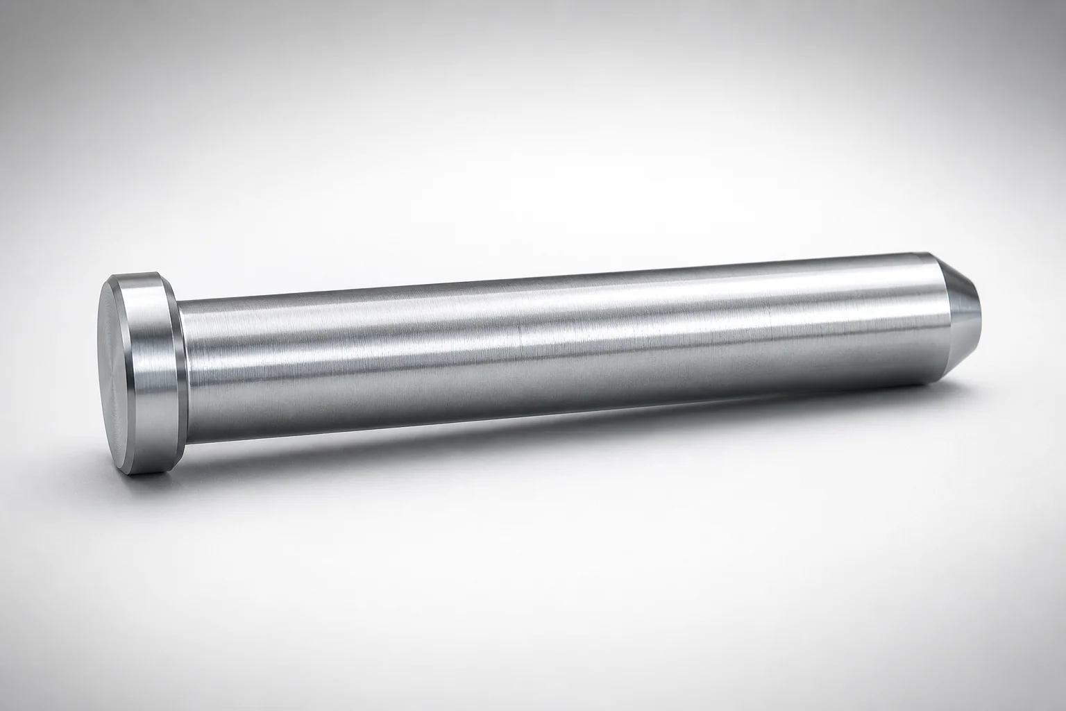
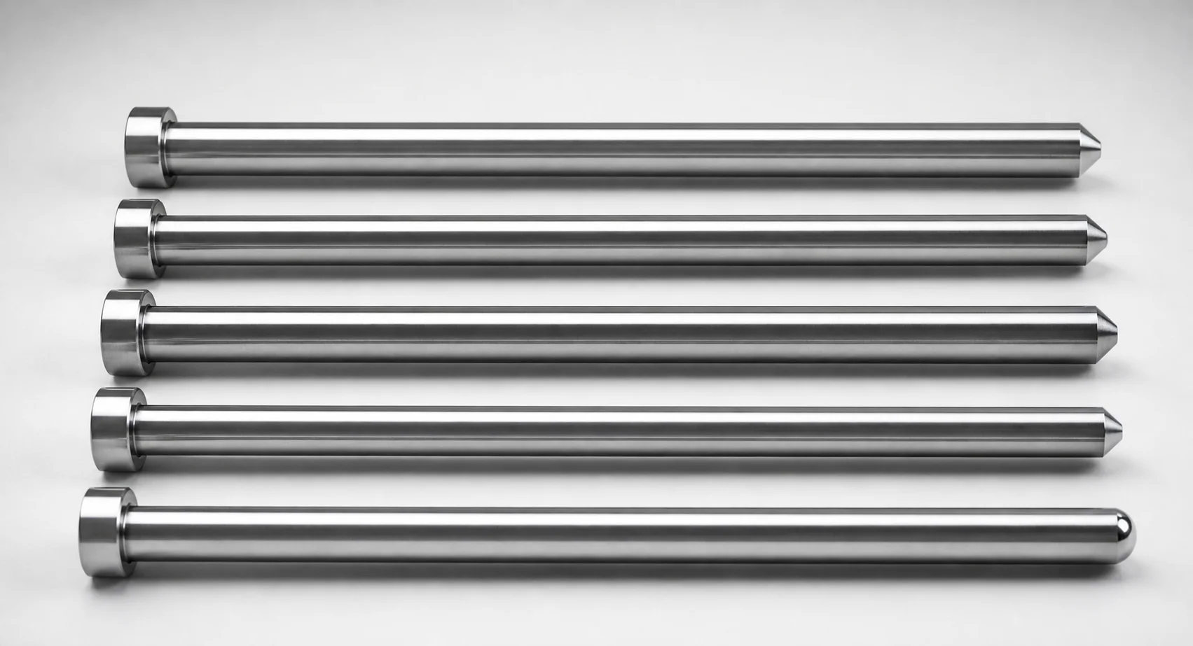
JIS Standard SKD61 Steel Gas Release Straight Core Pins Flat-Sided
Gas release straight core pins (SKD61 steel) are designed for stable ejector alignment with a flat-sided head and an internal venting/cooling-hole option for improved mold exhaust. The nitrided finish supports long service life under repeated press cycles.
- Built-in gas vent feature supports efficient mold gas release during operation
- SKD61 steel construction with nitrided surface treatment enhances wear resistance
- Supports sleeve fit-up with H7-reference inner diameter compatibility for consistent assembly
- JIS-standard core pin design for practical use in die and injection mold tooling
Specifications
60 configurations available
| Head Thickness | Shaft Diameter Tolerance | D/P (Shaft Diameter) (mm) | Tip Shape | C (C chamfering width on the tip) (mm) | K (Taper angle) (°) | L (L dimension) (mm) | R (Tip R chamfering) (mm) | S (Tip tapered width) (mm) | type |
|---|---|---|---|---|---|---|---|---|---|
| 6mm(JIS) | -0.01/-0.02 | 6 | B | - | - | 70 ~ 150 | - | - | - |
| 6mm(JIS) | -0.01/-0.02 | 7 | B | - | - | 70 ~ 200 | - | - | - |
| 8mm(JIS) | -0.01/-0.02 | 8 | B | - | - | 70 ~ 250 | - | - | - |
| 8mm(JIS) | -0.01/-0.02 | 10 | B | - | - | 70 ~ 250 | - | - | - |
| 8mm(JIS) | -0.01/-0.02 | 12 | B | - | - | 70 ~ 250 | - | - | - |
| 8mm(JIS) | -0.01/-0.02 (Reference tolerance) | 15 | B | - | - | 70 ~ 250 | - | - | - |
| 8mm(JIS) | -0.01/-0.02 (Reference tolerance) | 16 | B | - | - | 70 ~ 250 | - | - | - |
| 6mm(JIS) | -0.01/-0.02 | 6 | C | 0.1 ~ 2.9 | - | 70 ~ 150 | - | - | - |
| 6mm(JIS) | -0.01/-0.02 | 7 | C | 0.1 ~ 3.4 | - | 70 ~ 200 | - | - | - |
| 8mm(JIS) | -0.01/-0.02 | 8 | C | 0.1 ~ 3.9 | - | 70 ~ 250 | - | - | - |
| 8mm(JIS) | -0.01/-0.02 | 10 | C | 0.1 ~ 4.9 | - | 70 ~ 250 | - | - | - |
| 8mm(JIS) | -0.01/-0.02 | 12 | C | 0.1 ~ 5.9 | - | 70 ~ 250 | - | - | - |
| 8mm(JIS) | -0.01/-0.02 (Reference tolerance) | 15 | C | 0.1 ~ 7.4 | - | 70 ~ 250 | - | - | - |
| 8mm(JIS) | -0.01/-0.02 (Reference tolerance) | 16 | C | 0.1 ~ 7.9 | - | 70 ~ 250 | - | - | - |
| 6mm(JIS) | -0.01/-0.02 | 6 | G | - | 45 ~ 89 | 70 ~ 150 | - | - | - |
| 6mm(JIS) | -0.01/-0.02 | 7 | G | - | 45 ~ 89 | 70 ~ 200 | - | - | - |
| 8mm(JIS) | -0.01/-0.02 | 8 | G | - | 45 ~ 89 | 70 ~ 250 | - | - | - |
| 8mm(JIS) | -0.01/-0.02 | 10 | G | - | 45 ~ 89 | 70 ~ 250 | - | - | - |
| 8mm(JIS) | -0.01/-0.02 | 12 | G | - | 45 ~ 89 | 70 ~ 250 | - | - | - |
| 8mm(JIS) | -0.01/-0.02 (Reference tolerance) | 15 | G | - | 45 ~ 89 | 70 ~ 250 | - | - | - |
| 8mm(JIS) | -0.01/-0.02 (Reference tolerance) | 16 | G | - | 45 ~ 89 | 70 ~ 250 | - | - | - |
| 6mm(JIS) | -0.01/-0.02 | 6 | R | - | - | 70 ~ 150 | 0.2 ~ 2.9 | - | - |
| 6mm(JIS) | -0.01/-0.02 | 7 | R | - | - | 70 ~ 200 | 0.2 ~ 3.4 | - | - |
| 8mm(JIS) | -0.01/-0.02 | 8 | R | - | - | 70 ~ 250 | 0.2 ~ 3.9 | - | - |
| 8mm(JIS) | -0.01/-0.02 | 10 | R | - | - | 70 ~ 250 | 0.2 ~ 4.9 | - | - |
| 8mm(JIS) | -0.01/-0.02 | 12 | R | - | - | 70 ~ 250 | 0.2 ~ 5.9 | - | - |
| 8mm(JIS) | -0.01/-0.02 (Reference tolerance) | 15 | R | - | - | 70 ~ 250 | 0.2 ~ 7.4 | - | - |
| 8mm(JIS) | -0.01/-0.02 (Reference tolerance) | 16 | R | - | - | 70 ~ 250 | 0.2 ~ 7.9 | - | - |
| 6mm(JIS) | -0.01/-0.02 | 6 | T | - | 1 ~ 45 | 70 ~ 150 | - | 0.1 ~ 12 | - |
| 6mm(JIS) | -0.01/-0.02 | 7 | T | - | 1 ~ 45 | 70 ~ 200 | - | 0.1 ~ 14 | - |
| 8mm(JIS) | -0.01/-0.02 | 8 | T | - | 1 ~ 45 | 70 ~ 250 | - | 0.1 ~ 16 | - |
| 8mm(JIS) | -0.01/-0.02 | 10 | T | 0.1 ~ 4.9 | - | 70 ~ 250 | - | - | - |
| 8mm(JIS) | -0.01/-0.02 | 12 | T | - | 1 ~ 45 | 70 ~ 250 | - | 0.1 ~ 24 | - |
| 8mm(JIS) | -0.01/-0.02 (Reference tolerance) | 15 | T | - | 1 ~ 45 | 70 ~ 250 | - | 0.1 ~ 30 | - |
| 8mm(JIS) | -0.01/-0.02 (Reference tolerance) | 16 | T | - | 1 ~ 45 | 70 ~ 250 | - | 0.1 ~ 32 | - |
| 4mm(T4) | -0.01/-0.02 | 6 | B | - | - | 70 ~ 150 | - | - | - |
| 4mm(T4) | -0.01/-0.02 | 7 | B | - | - | 70 ~ 200 | - | - | - |
| 4mm(T4) | -0.01/-0.02 | 8 | B | - | - | 70 ~ 250 | - | - | - |
| 4mm(T4) | -0.01/-0.02 | 10 | B | - | - | 70 ~ 250 | - | - | - |
| 4mm(T4) | -0.01/-0.02 | 12 | B | - | - | 70 ~ 250 | - | - | - |
| 4mm(T4) | -0.01/-0.02 | 6 | C | 0.1 ~ 2.9 | - | 70 ~ 150 | - | - | - |
| 4mm(T4) | -0.01/-0.02 | 7 | C | 0.1 ~ 3.4 | - | 70 ~ 200 | - | - | - |
| 4mm(T4) | -0.01/-0.02 | 8 | C | 0.1 ~ 3.9 | - | 70 ~ 250 | - | - | - |
| 4mm(T4) | -0.01/-0.02 | 10 | C | 0.1 ~ 4.9 | - | 70 ~ 250 | - | - | - |
| 4mm(T4) | -0.01/-0.02 | 12 | C | 0.1 ~ 5.9 | - | 70 ~ 250 | - | - | - |
| 4mm(T4) | -0.01/-0.02 | 6 | G | - | 45 ~ 89 | 70 ~ 150 | - | - | - |
| 4mm(T4) | -0.01/-0.02 | 7 | G | - | 45 ~ 89 | 70 ~ 200 | - | - | - |
| 4mm(T4) | -0.01/-0.02 | 8 | G | - | 45 ~ 89 | 70 ~ 250 | - | - | - |
| 4mm(T4) | -0.01/-0.02 | 10 | G | - | 45 ~ 89 | 70 ~ 250 | - | - | - |
| 4mm(T4) | -0.01/-0.02 | 12 | G | - | 45 ~ 89 | 70 ~ 250 | - | - | - |
Product Guide
Application Scenarios+
These SKD61 gas release straight core pins are used in injection mold tooling where stable ejection alignment and reliable venting are required, particularly in multi-cavity and high-cycle systems. The flat-sided head helps improve gas evacuation around the core pin interface, reducing trapped air and potential burn marks while maintaining consistent core movement.
- Automotive connector and sensor housings: Flat-sided head and integrated gas release support cleaner molding of fine features and thin-wall sections, where venting stability directly affects surface finish.
- Consumer electronics enclosures: Nitrided pin surfaces resist wear from repeated press cycles, helping maintain dimensional stability of the ejector/core alignment over long runs.
- Appliance and industrial plastic parts: The straight geometry and option for internal venting/cooling-hole arrangement support effective exhaust during filling and packing, improving cycle repeatability.
The nitrided SKD61 variant is suited for these applications because it combines tooling-grade toughness with improved surface wear resistance under frequent actuation.
Material & Process Details+
The pin body is made from JIS Standard SKD61 steel, commonly used in hot-work and tooling applications (AISI H13 equivalent family). SKD61 is selected for good balance of toughness and heat-check / wear resistance during repeated thermal and mechanical loading.
After machining, the surface is finished with a nitrided treatment (as indicated by the product variant). Nitriding increases surface hardness and wear resistance while keeping the core comparatively tougher for shock resistance—this is a practical trade-off versus fully hardened high-wear steels.
- Expected performance: enhanced resistance to sliding/press-wear at the guide and pin contact areas.
- Heat treatment state: nitrided finish (surface-treated) for improved service life in high-cycle molds.
Because the provided data specifies nitriding but not the exact bulk hardness value in HRC, hardness should be verified from the manufacturer’s heat-treat/acceptance records for your specific batch.
Sizing & Selection Guide+
Select the pin based on the shaft diameter (D/P), length (L), and head thickness to ensure proper core pin engagement and venting clearance in the mold.
- Choose D/P: available shaft diameter range is 6 ~ 16 mm. Match this to the core pin bore/corresponding sleeve inner diameter, using the product note that it supports H7-reference inner diameter compatibility for assembly.
- Choose L: available length options include 70 ~ 150 mm, 70 ~ 200 mm, and 70 ~ 250 mm. Confirm core travel envelope and ejector path so the pin fully engages without interference.
- Head thickness: JIS head thickness options are 4 mm(T4), 6 mm, or 8 mm (per the provided variants). Select head thickness to match the stripper/ejector stack-up and bearing/stop features.
Also confirm the tip geometry selection (B, C, G, R, T) and associated dimensions such as K (45–89°, 1–45°), C 0.1 mm, R 0.2 mm, and S up to 0.1–32 mm to maintain correct clearance to the mold opening and core interface.
For shaft diameter tolerance, use the reference tolerance -0.01/-0.02 when checking fit between the pin and the H7-referenced bore.
Frequently Asked Questions
How does the flat-sided head improve venting in gas release straight core pin applications?+
The flat-sided head improves gas evacuation around the core pin interface during molding. This helps reduce trapped air and associated surface defects at or near the pin area.
In tooling where an internal venting/cooling-hole option is used, the flat geometry further supports more consistent exhaust conditions around the straight core pin.
What steel and surface treatment does this gas release core pin use, and how does nitriding affect wear resistance?+
The pin is made from JIS Standard SKD61 steel and includes a nitrided finish as stated for this variant.
Nitriding primarily enhances surface wear resistance while helping retain adequate toughness in the pin core. For exact hardness in HRC, refer to the heat-treat/acceptance data for your specific SKD61 nitriding lot.
What shaft diameter and tolerance range should I use when matching the pin to an H7-referenced bore?+
The product data specifies shaft diameter range D/P = 6 ~ 16 mm with a reference shaft diameter tolerance of -0.01/-0.02.
The description notes compatibility with H7-reference inner diameter. When sizing the mold bore, use your H7 tolerance limits together with the pin’s -0.01/-0.02 to verify assembly fit and clearance.
Which length options (L) are available, and how do I ensure the pin clears the mold/ejector stack-up?+
Available L ranges are 70 ~ 150 mm, 70 ~ 200 mm, and 70 ~ 250 mm (depending on the configuration). Select L based on your core depth and ejector travel envelope so the tip does not interfere with shutoff surfaces.
After selecting L, verify head thickness options (4 mm(T4), 6 mm, or 8 mm) against your stripper/ejector stack-up and stops.
How do I select tip geometry (B, C, G, R, T) and angles (K) for clearance at the core interface?+
The tip shape can be selected as B, C, G, R, or T, with taper angle K offered in 45–89° and 1–45° ranges.
Confirm that the associated tip dimensions—such as C = 0.1 mm and R = 0.2 mm, plus the tapered width S (0.1 up to the specified max)—fit your required clearance to the mold opening and core interface.
Related Products
Need Custom Specifications?
Our engineering team can help with custom configurations, material selection, and volume pricing.