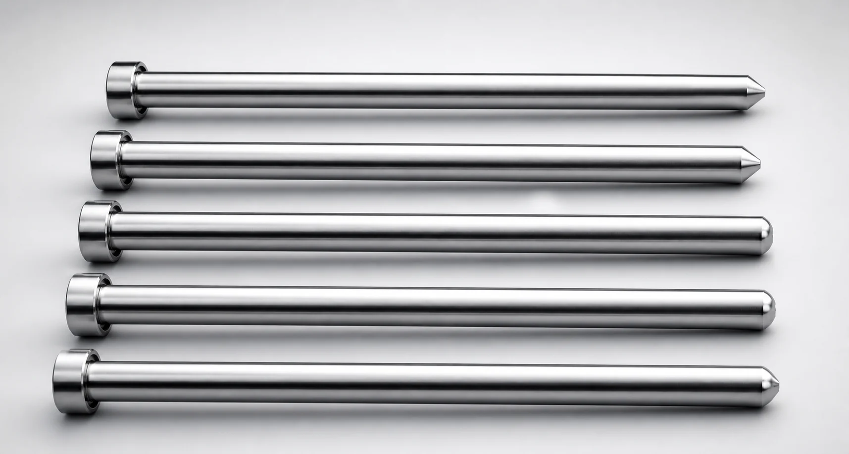
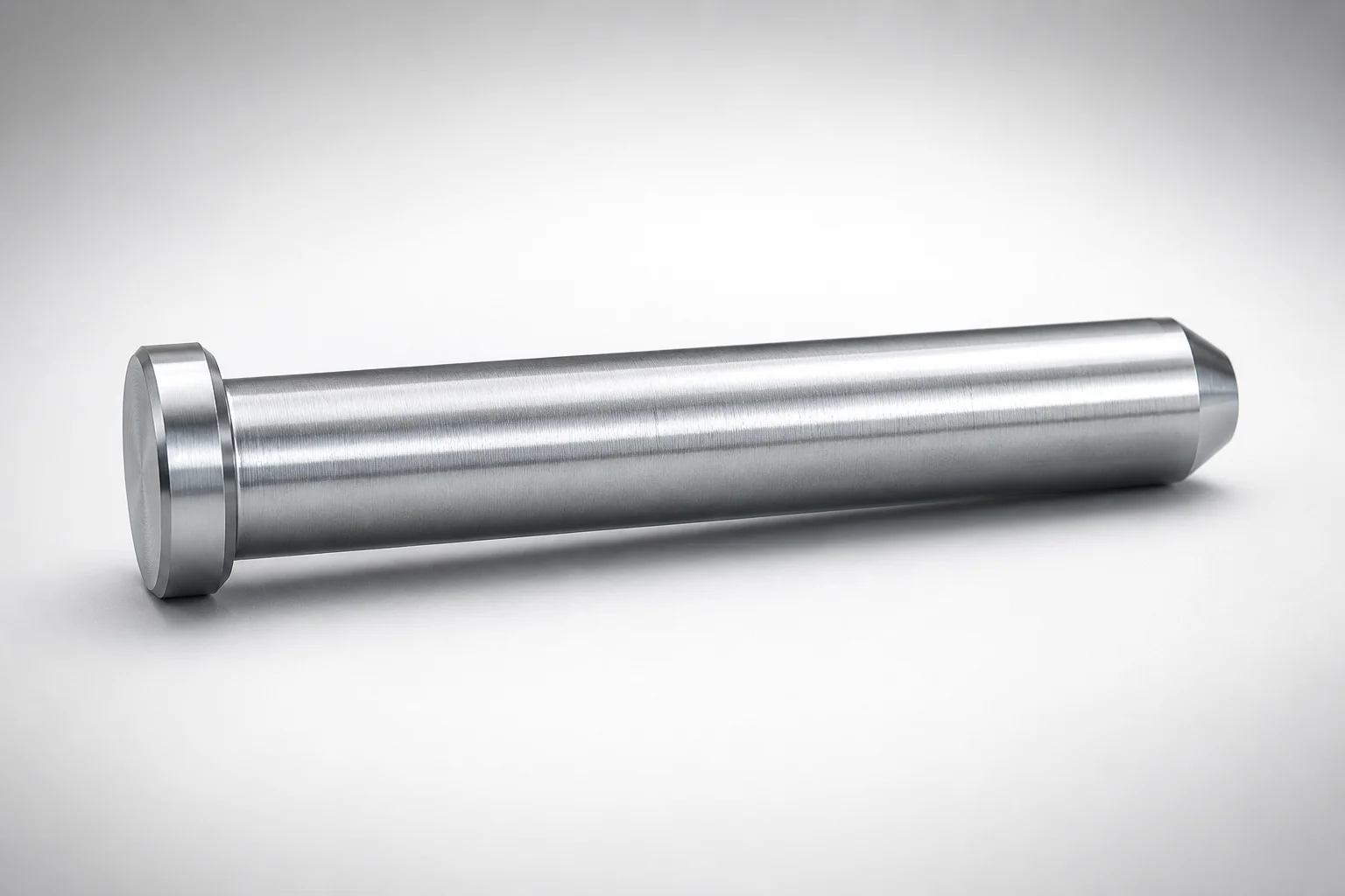
JIS Standard M2 Steel Straight Center Pins with Tip Processed
Straight Center Pins with Tip Processed (M2 steel, SKH51 construction) are designed to improve mold locating accuracy during ejection while using a processed tip to support reliable centering. They are manufactured to JIS specifications for consistent performance in production tooling.
- Processed tip design supports accurate centering for stable ejector operation
- SKH51 steel quenched and hardened for abrasion resistance
- Compatible sleeve fit with H7 inner diameter tolerance (+0.01/0)
- JIS manufacturing supports repeatable assembly in precision molds
Specifications
260 configurations available
| Head Thickness | Shaft Diameter Tolerance | D/P (Shaft Diameter) (mm) | Tip Shape | Compatible Ejector Sleeve Inner Diameter Tolerance | No. (Nominal diameter) (mm) | C (C chamfering width on the tip) (mm) | K (Taper angle) (°) | L (L dimension) (mm) | R (Tip R chamfering) (mm) | S (Tip tapered width) (mm) | type |
|---|---|---|---|---|---|---|---|---|---|---|---|
| 4mm(T4) | 0/-0.005 | 0.8 ~ 0.99 | B | - | 1 | - | - | 50 ~ 200 | - | - | - |
| 4mm(T4) | 0/-0.005 | 1 ~ 1.9 | B | - | 1.5 | - | - | 50 ~ 250 | - | - | - |
| 4mm(T4) | 0/-0.005 | 1.5 ~ 1.99 | B | - | 2 | - | - | 50 ~ 250 | - | - | - |
| 4mm(T4) | 0/-0.005 | 2 ~ 2.49 | B | - | 2.5 | - | - | 50 ~ 250 | - | - | - |
| 4mm(T4) | 0/-0.005 | 2.5 ~ 2.99 | B | - | 3 | - | - | 50 ~ 300 | - | - | - |
| 4mm(T4) | 0/-0.005 | 3 ~ 3.49 | B | - | 3.5 | - | - | 50 ~ 300 | - | - | - |
| 4mm(T4) | 0/-0.005 | 3.5 ~ 3.99 | B | - | 4 | - | - | 50 ~ 300 | - | - | - |
| 4mm(T4) | 0/-0.005 | 4 ~ 4.49 | B | - | 4.5 | - | - | 50 ~ 300 | - | - | - |
| 4mm(T4) | 0/-0.005 | 4.5 ~ 4.99 | B | - | 5 | - | - | 50 ~ 350 | - | - | - |
| 4mm(T4) | 0/-0.005 | 5 ~ 5.49 | B | - | 5.5 | - | - | 50 ~ 350 | - | - | - |
| 4mm(T4) | 0/-0.005 | 5.5 ~ 5.99 | B | - | 6 | - | - | 50 ~ 350 | - | - | - |
| 4mm(T4) | 0/-0.005 | 6 ~ 6.49 | B | - | 6.5 | - | - | 50 ~ 350 | - | - | - |
| 4mm(T4) | 0/-0.005 | 6.5 ~ 6.99 | B | - | 7 | - | - | 50 ~ 350 | - | - | - |
| 4mm(T4) | 0/-0.005 | 7 ~ 7.99 | B | - | 8 | - | - | 50 ~ 350 | - | - | - |
| 4mm(T4) | 0/-0.005 | 8 ~ 9.99 | B | - | 10 | - | - | 50 ~ 350 | - | - | - |
| 4mm(T4) | 0/-0.005 | 10 ~ 11.99 | B | - | 12 | - | - | 50 ~ 350 | - | - | - |
| 4mm(T4) | 0/-0.005 | 0.8 ~ 0.99 | C | - | 1 | 0.1 ~ 0.4 | - | 50 ~ 200 | - | - | - |
| 4mm(T4) | 0/-0.005 | 1 ~ 1.49 | C | - | 1.5 | 0.1 ~ 0.6 | - | 50 ~ 250 | - | - | - |
| 4mm(T4) | 0/-0.005 | 1.5 ~ 1.99 | C | - | 2 | 0.1 ~ 0.9 | - | 50 ~ 250 | - | - | - |
| 4mm(T4) | 0/-0.005 | 2 ~ 2.49 | C | - | 2.5 | 0.1 ~ 1.1 | - | 50 ~ 250 | - | - | - |
| 4mm(T4) | 0/-0.005 | 2.5 ~ 2.99 | C | - | 3 | 0.1 ~ 1.4 | - | 50 ~ 300 | - | - | - |
| 4mm(T4) | 0/-0.005 | 3 ~ 3.49 | C | - | 3.5 | 0.1 ~ 1.6 | - | 50 ~ 300 | - | - | - |
| 4mm(T4) | 0/-0.005 | 3.5 ~ 3.99 | C | - | 4 | 0.1 ~ 1.9 | - | 50 ~ 300 | - | - | - |
| 4mm(T4) | 0/-0.005 | 4 ~ 4.49 | C | - | 4.5 | 0.1 ~ 2.1 | - | 50 ~ 300 | - | - | - |
| 4mm(T4) | 0/-0.005 | 4.5 ~ 4.99 | C | - | 5 | 0.1 ~ 2.4 | - | 50 ~ 350 | - | - | - |
| 4mm(T4) | 0/-0.005 | 5 ~ 5.49 | C | - | 5.5 | 0.1 ~ 2.6 | - | 50 ~ 350 | - | - | - |
| 4mm(T4) | 0/-0.005 | 5.5 ~ 5.99 | C | - | 6 | 0.1 ~ 2.9 | - | 50 ~ 350 | - | - | - |
| 4mm(T4) | 0/-0.005 | 6 ~ 6.49 | C | - | 6.5 | 0.1 ~ 3.1 | - | 50 ~ 350 | - | - | - |
| 4mm(T4) | 0/-0.005 | 6.5 ~ 6.99 | C | - | 7 | 0.1 ~ 3.4 | - | 50 ~ 350 | - | - | - |
| 4mm(T4) | 0/-0.005 | 7 ~ 7.99 | C | - | 8 | 0.1 ~ 3.9 | - | 50 ~ 350 | - | - | - |
| 4mm(T4) | 0/-0.005 | 8 ~ 9.99 | C | - | 10 | 0.1 ~ 4.9 | - | 50 ~ 350 | - | - | - |
| 4mm(T4) | 0/-0.005 | 10 ~ 11.99 | C | - | 12 | 0.1 ~ 5.9 | - | 50 ~ 350 | - | - | - |
| 4mm(T4) | 0/-0.005 | 0.8 ~ 0.99 | G | - | 1 | - | 45 ~ 89 | 50 ~ 200 | - | - | - |
| 4mm(T4) | 0/-0.005 | 1 ~ 1.49 | G | - | 1.5 | - | 45 ~ 89 | 50 ~ 250 | - | - | - |
| 4mm(T4) | 0/-0.005 | 1.5 ~ 1.99 | G | - | 2 | - | 45 ~ 89 | 50 ~ 250 | - | - | - |
| 4mm(T4) | 0/-0.005 | 2 ~ 2.49 | G | - | 2.5 | - | 45 ~ 89 | 50 ~ 250 | - | - | - |
| 4mm(T4) | 0/-0.005 | 2.5 ~ 2.99 | G | - | 3 | - | 45 ~ 89 | 50 ~ 300 | - | - | - |
| 4mm(T4) | 0/-0.005 | 3 ~ 3.49 | G | - | 3.5 | - | 45 ~ 89 | 50 ~ 300 | - | - | - |
| 4mm(T4) | 0/-0.005 | 3.5 ~ 3.99 | G | - | 4 | - | 45 ~ 89 | 50 ~ 300 | - | - | - |
| 4mm(T4) | 0/-0.005 | 4 ~ 4.49 | G | - | 4.5 | - | 45 ~ 89 | 50 ~ 300 | - | - | - |
| 4mm(T4) | 0/-0.005 | 4.5 ~ 4.99 | G | - | 5 | - | 45 ~ 89 | 50 ~ 350 | - | - | - |
| 4mm(T4) | 0/-0.005 | 5 ~ 5.49 | G | - | 5.5 | - | 45 ~ 89 | 50 ~ 350 | - | - | - |
| 4mm(T4) | 0/-0.005 | 5.5 ~ 5.99 | G | - | 6 | - | 45 ~ 89 | 50 ~ 350 | - | - | - |
| 4mm(T4) | 0/-0.005 | 6 ~ 6.49 | G | - | 6.5 | - | 45 ~ 89 | 50 ~ 350 | - | - | - |
| 4mm(T4) | 0/-0.005 | 6.5 ~ 6.99 | G | - | 7 | - | 45 ~ 89 | 50 ~ 350 | - | - | - |
| 4mm(T4) | 0/-0.005 | 7 ~ 7.99 | G | - | 8 | - | 45 ~ 89 | 50 ~ 350 | - | - | - |
| 4mm(T4) | 0/-0.005 | 8 ~ 9.99 | G | - | 10 | - | 45 ~ 89 | 50 ~ 350 | - | - | - |
| 4mm(T4) | 0/-0.005 | 10 ~ 11.99 | G | - | 12 | - | 45 ~ 89 | 50 ~ 350 | - | - | - |
| 4mm(T4) | 0/-0.005 | 0.8 ~ 0.99 | R | - | 1 | - | - | 50 ~ 200 | 0.2 ~ 0.4 | - | - |
| 4mm(T4) | 0/-0.005 | 1 ~ 1.49 | R | - | 1.5 | - | - | 50 ~ 250 | 0.2 ~ 0.6 | - | - |
Product Guide
Application Scenarios+
Where it’s used: Tipped straight center pins are installed in ejector mechanisms to control locating accuracy between the core-side ejector set and the mating ejector sleeve.
Scenario 1 — Automotive connector and sensor housings: In high-cycle injection molding, consistent ejection alignment helps prevent scuffing and uneven wear on ejector components. The processed tip promotes stable centering at initial engagement, and the controlled sleeve fit (H7 inner diameter tolerance) supports repeatable assembly.
Scenario 2 — Medical device housings and caps: Tight alignment reduces positional variation during ejection, which is critical when tolerances for cosmetic surfaces and snap-fit features are tight. Tip processing improves centering reliability, helping maintain stable ejector operation.
Scenario 3 — Precision electronics enclosures: For small-diameter ejector trains (e.g., D/P range 0.8–10 mm), the JIS specification manufacturing supports consistent fit across production builds. The SKH51 (M2 steel construction) abrasion-resistant construction is well-suited for alignment-critical, wear-exposed ejector interfaces.
- Tip-processed geometry improves centering stability on first contact
- JIS standard production supports consistent mold-to-mold repeatability
- H7 sleeve compatibility supports a controlled, predictable locating fit
Material & Process Details+
This series uses an SKH51 construction, which is commonly used as an AISI M2-equivalent high-speed steel for wear resistance in cutting and tooling applications. For these straight center pins, the steel is quenched and hardened to achieve high surface hardness for long service life at the ejector alignment interface.
- Hardness (HRC): The intended hardened condition targets abrasion resistance; exact HRC is not specified in the provided data, so hardness should be verified against the incoming material certificate for your lot.
- Wear resistance vs. toughness trade-off: Hardened M2-class steels improve resistance to fretting and sliding wear, while toughness is typically lower than annealed grades—important for pins that see repeated impact during ejection.
- Heat treatment state: Quenched & hardened construction (no nitriding or tempering values provided).
If you need higher impact tolerance, you’d typically consider alternative base steels or modified heat treatments; however, the H7-compatible, wear-exposed centering function here is designed around the SKH51 hardened abrasion-resistant approach.
Sizing & Selection Guide+
Select by shaft diameter and fit first: Match the pin’s D/P (shaft diameter) range 0.8–10 mm to the corresponding ejector sleeve inner diameter. This series is designed for a compatible ejector sleeve inner diameter tolerance of +0.01/0 (H7), supporting a controlled locating fit.
Choose the correct nominal diameter: Use No. (nominal diameter) 1–12 mm and confirm it aligns with your sleeve bore selection for the required clearance and repeatability.
- Check diameter tolerance: Shaft diameter tolerance options are 0/−0.005 and −0.01/−0.02, which affects clearance under H7 sleeve conditions.
- Set length: Select the L dimension 50–200, 50–250, 50–300, or 50–350 mm based on required reach within the mold stack and ejector stroke.
- Confirm tip geometry: Pick Tip shape (B, C, G, R, T) and verify chamfer/taper features such as K (taper angle) 45–89° or 1–45°, plus R (tip chamfer radius) 0.2 mm and S 0.1 mm.
Tip-to-sleeve engagement: The processed tip is intended to center on entry; ensure the chosen tip shape/angle complements the sleeve bore length and the initial engagement zone to reduce misalignment.
Frequently Asked Questions
What sleeve fit tolerance should I design for when using these tipped straight center pins?+
This series is specified as compatible with an ejector sleeve inner diameter tolerance of +0.01/0, i.e., H7. When matching clearances, select the pin shaft diameter (D/P) within the 0.8–10 mm range and confirm the pin’s shaft diameter tolerance (either 0/−0.005 or −0.01/−0.02) against your sleeve bore.
Which shaft diameter tolerance option (0/−0.005 vs −0.01/−0.02) is better for tighter centering?+
Tighter centering generally corresponds to a smaller effective clearance, which you achieve by choosing the appropriate shaft diameter tolerance option relative to the sleeve’s H7 (+0.01/0) bore. If you need the least clearance, consider the −0.01/−0.02 tolerance option in conjunction with your measured sleeve bore and expected thermal/housing deflection.
Final fit should be validated using actual mold steel temperatures and assembly conditions, since the provided data does not include process temperature offsets.
Do these center pins use SKH51 (M2-equivalent) and what heat treatment condition should I expect?+
Yes. The series specifies an SKH51 construction and states it is quenched and hardened for abrasion resistance. The material-property hardness in HRC is not explicitly provided in the dataset, so you should request the material certificate for the exact hardness for your purchase lot.
How do I choose the correct tip shape and taper angle for my ejection alignment requirement?+
Select the Tip shape from B, C, G, R, T and match the K taper angle to your centering and engagement needs: options include 45–89° and 1–45°. The dataset also fixes certain tip geometry features such as R = 0.2 mm and S = 0.1 mm.
For stable initial centering, ensure the chosen tip angle/shape fits the sleeve’s lead-in zone without causing binding.
What length range (L) is available for different mold stackups?+
The L dimension is offered in multiple ranges: 50–200, 50–250, 50–300, and 50–350 mm. Choose the range that provides full engagement across the ejector travel while maintaining clearance to adjacent components.
Also confirm the head thickness option you need: 4 mm (T4), 6 mm, or 8 mm as applicable.
Related Products
Need Custom Specifications?
Our engineering team can help with custom configurations, material selection, and volume pricing.